Rain Alarm Circuit – Snow, Water and Rain Detector Project
Rain Alarm Circuit – Water, Rain and Snow Defector using Rain Sensor and 555 Timer IC
In a world full of automation, everyone wants to stay smart and productive. And, water harvesting can also be achieved easily with the help of automation. Here in this article, we will be discussing the Rain Alarm project which has a great significance in harvesting rainwater. The circuit helps to detect the rain by giving an alarm while you are sitting inside the home, so that you can take necessary action. It totally helps in avoiding the unnecessary headache of keeping an eye outside your window in the rainy season to see when it is going to rain. To save your time money and effort let’s start with the process of making a simple and cost effective rain alarm circuit in the easiest way.
Why We Need Rain Alarm?
This circuit enables you to manage your outside settings when it rains. You can close your windows or get ready for rain water harvesting after hearing the alarm. With some small modification the circuit can also be used as water level indicator, agriculture field irrigation system etc. The biggest advantage of this circuit is that it’s simple, reliable and consumes less power.
Rain Alarm Circuit consists of three main components that include Rain sensor, 555 Timer IC and a buzzer. The heart of rain alarm circuit is rain sensor which is used to detect the presence of water.
When rain drops falls on the sensor, it creates a conducting path and triggers the 555 Timer IC. Once the timer IC is triggered, it will activate the alarm. The biggest advantage of using rain sensor in the circuit is that it is relatively cheap and highly reliable. You don’t need to rush for purchasing the one in fact, you can make rain sensor at home in simple way suggested in this article. So, before starting with the project, let me brief you about the design, circuit diagram, working and application of rain sensor.
- Related Project: Water Level Indicator Circuit Diagram- Two Simple Projects
The circuit mainly works on the principle that normal water conducts some amount of electricity, although rain water or natural water is not pure. Being able to detect rain due to use of rain sensor, this circuit can be used in various other fields where you want to detect water.
Also, we will be guiding you step by step to design a rain alarm sensor with the help of simple and cost effective components.
Rain Sensor
 The rain sensor is a switching device which usually activated by rainfall. This automated device is mounted outdoor so that it can sense rain without any obstruction. You, can purchase a rain sensor from your nearest electronic store or you can make one at home. Read More about Capacitive Sensor as Humidity Sensor.
- Related Project: Smart Irrigation System – Circuit Diagram and Code
Now, to make a rain sensor at home you just need to collect the following components-
- Aluminium wire
- Mica board
Make sure that the mica board is made completely flat. Place the aluminium wire over the mica board ensuring that there will be no space between the wire and board.
- Related Project: Traffic Light Control Electronic Project using IC 4017 & 555 Timer
We can also use copper board in place of mica board. But then you have to clean the copper board on regular basis to avoid the corrosion due to presence of water. That’s why we prefer to use mica.
Rain Sensor Working
When there is no rain, the resistance between the wires of rain sensor will be very high and there will be no conduction between the wires on sensor.
When the rain drop falls on the sensor, it will form a conductive path between the wires and the resistance between wires will decreases. At this point, the wires on sensor board will start conducting current.
Simply, this sensor is working as a switch, so whenever water is present on the sensor it allow the current to pass through it (ON condition). And, if there is no water then it discontinues the flow of current (OFF condition).
Related Project: Clap Switch Circuit Electronic Project Using 555 Timer
Applications
- Rain Detector
- Professional satellite communication antennas
- Support for automatic mode of windscreen wipers
- Home automation
- Automobiles
Rain Alarm Circuit
We hope that now you may have a good knowledge of rain sensor and its working. The second main component of this circuit is 555 Timer IC. This 8 pin 555 Timer IC generally operates in three modes namely A-sable mode, Mono-Stable mode and Bi-Stable mode. In rain alarm circuit, the main reason behind using 555 Timer IC is to trigger the buzzer for producing oscillating sound.
Before starting with Rain alarm circuit design process, go through the below mentioned part list and arrange the required components as per the given specifications.
- Related Project: PCB Design of LED Flasher Circuit. Step by Step
Required Components for Rain Detector Circuit
- 555 Timer IC
- Rain Sensor
- Transistors- 1xBC548 , 2x 2N2222 NPN
- Capacitor- 1x22uf, 2x100uf
- Diode- 1xN4007 PN junction diode
- Ceramic capacitor- 1x10nf ,1×100 pf
- Resistors- 1×68 k Ohm, 2×3.3 k Ohm, 1×470 k Ohm, 1×10 k Ohm, 1×330 k Ohm, 1×220 k Ohm
- LED
- Connecting wires
- Breadboard
- 12 V power supply
Related Post: LED String/Strip Circuit Diagram Using PCR-406
Block Diagram of Rain Alarm Circuit
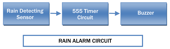
Before understanding the circuit with its circuit diagram, let’s give you a rough idea of rain alarm circuit and its working with the help of block diagram. There are mainly two components on the circuits namely 555 Timer IC, rain sensor which plays a pivotal role in driving the circuit. Whenever the rain sensor detects rain, it sends the signal to 555 Timer IC which is configured in A-Stable mode. The triggered IC will start the buzzer which is indicating the raining condition. The alarm sound enables you to make the necessary arrangements accordingly.
Related Project: How to Make an LED Project with ATMega Microcontroller?
Rain Alarm Circuit Diagram
After collecting all the required parts, connect the components as shown below. Here, 555 Timer IC has been configured in A-stable mode so that buzzer can produce periodically ON and OFF sound.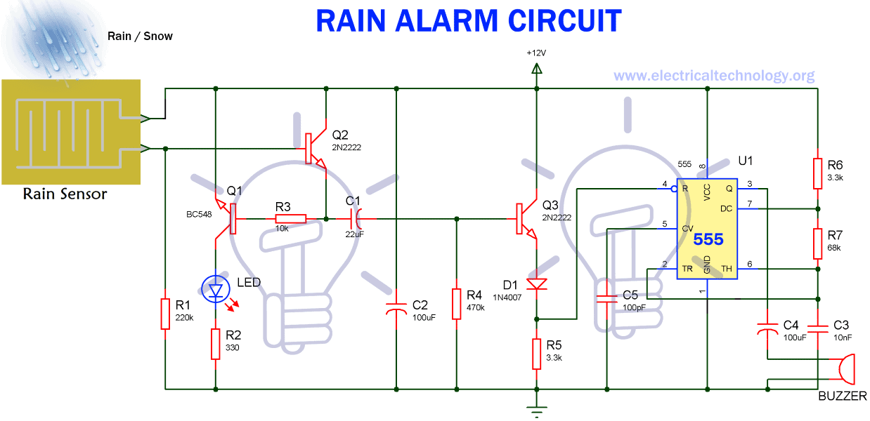
Pin 5 is connected to ground through 100pf capacitor.BC548 transistor is wired as a switch. Resistor R3 is connected to control the collector of transistor and Resistor R4 is pull-down resistor. Capacitor C4 is connected with the Pin 3 of timer and speaker. The reset pin of 555 Timer IC is connected to the emitter of Q3.The LED is connected with emitter of transistor Q1.The output frequency of 555 Timer IC can be measured using the below method.
- Related Project: Emergency LED Light Circuit – LED-716 Emergency Light Schematic.
Output frequency= 1.44/ (R3 +2xR4)*C1) = 0.72HZ
Working of Rain Alarm Circuit
The 555 timer IC is configured in A-stable mode. Here, the buzzer is connected with output of 555 Timer IC which means that when the output of 555 Timer is high the buzzer will turn ON and when the output of 555 Timer is low then buzzer will be turned OFF. You can also change the buzzer beep frequency using the above equation.
When the rain drop falls on the sensor, the wires on sensor starts conducting and closes the path between supply and base of transistor Q2. Therefore, transistor Q1 and Q2 will turned ON, and by which the LED will also turn ON.
When the transistor Q2 is saturated, C1 will get shorted and make the transistor Q3 turned ON. At this point C1 will get charged by the resistor R4. As the transistor Q3 reaches the saturation mode, the reset pin of 555 Timer IC will get positive. As soon as the reset pin of timer gets the positive voltage, we can get a pulse signal at the output pin of 555 Timer IC. This will turn on the buzzer and make the alarm beep. The capacitor is connected to pin3 of 555 Timer IC and speaker is for blocking the DC signal. And, due to diode D2, no reverse current will be allowed from the timer.
Transistor Q3 will get into cut-off region after some time because of resistor R4 and capacitor C1.In result, there will be no positive voltage at reset pin of timer and buzzer will stop making sound. The sound of buzzer entirely depends on capacitor C1 and resistor R4.
And, if there is no rain, the sensor will not allow the current to pass through it. In result the 555 Timer IC will not be triggered and the buzzer remain in off condition.
There are two things which must be kept in mind while using the circuit. Rain sensor should be kept at an angle of 30 to 40 degree from ground to avoid the presence of water on sensor for long time. Second thing is that the LED will keep glowing until the rain stops and the buzzer will stop making sound automatically after some time.
Applications of Rain Alarm Circuit
- In irrigation, it can sense rain and inform the farmers on time
- In household, the circuit can work to start other automated rain water harvesting machines to harvest rain
- In automobile, it can start the wiper and inform the driver in case of rain.
- It can be used to detect chemical rain also.
- It can be used to boost strength of antenna and increase the signal strength to send and receive signals.
- Helps you save electricity
Bottom line-
Rain Alarm circuit is very useful and easy to design. In this article, we have discussed the cost effective rain alarm circuit with its circuit diagram, block diagram, working and its various applications. We hope that you will be able to design this highly reliable Rain Alarm circuit with ease. We have also explained the working of main components in the circuit i.e. – 555 Timer IC and Rain sensor in brief, that will help you understand the Woking of circuit more clearly.
- Related Project Fully Automatic Water Level Controller using SRF04


An interesting site I needed all about lighting the LED
I want rain alarm circuit using 555 timer project.