Infrared Motion Detector Circuit – Diagram, Working & Applications
Infrared Motion Detector – Circuit Diagram, Working and Applications
Nowadays, security is the first and foremost requirement of everyone’s life. In this article, we will be discussing a very useful and reliable security device called “Infrared Motion Detector Circuit”. The circuit can be used for detection of moving object or body, with the use of infrared sensors like IR, PIR, etc. Along with the PIR sensors, a simple circuit is used with it.
We will guide you step by step to design this circuit throughout our discussion. In this project, we will be using a passive infrared sensor (PIR) to sense the infrared emitted by a body or object.
PIR sensor detects the body heat of a person or object when it comes in close proximity. Whenever the sensor senses an object or body, it gives high at the output pin of the sensor. Through which we can control a LED, Buzzer or any home appliance.
For those who don’t even know what is PIR sensor? Read the below-mentioned description over the same.
What is a PIR Sensor?
PIR sensor stands for Passive Infrared Sensor. There are three IR regions on spectrum named as near-infrared (0.75-3um), mid-infrared (3-6um), and far infrared (higher than 6um). And, the infrared region of PIR sensor is from 0.75um to 1000um. PIR sensors module comes with three pins for interfacing with any microcontroller. One is a signal pin, second is for Ground and the third one is for power supply.

Whenever the motion is detected, the signal pin goes high. That means the sensor acts as digital output and gives “high or low” depending upon the situation.
PIR sensor doesn’t emit infrared signal by itself in fact, it detects infrared radiation coming from the body or object in its surrounding area. The output of the PIR sensor goes high when it detects infrared rays in its range.
Construction Of PIR Sensor
Coming to the discussion of materials used in the PIR sensor, there are mainly two important parts present in the PIR sensor module. The first one is the pyroelectric crystal and the second one is Fresnel lenses. The pyroelectric sensor detects the heat from an object or body and Fresnel lens widens the range of the sensor.

PIR converts the detected radiation electrical charge. This charge is further modified and improved by the built-in FET and given to the output pin of the device.
PIR sensor consists of two slots made up of materials sensitive to IR. As long as the sensor is inactive, the two slots sense the same amount of Infrared. Whenever the human body or object passes by, then the first slot of the sensor is being intercepted causing a positive differential change between two bisects. Again, when the object leaves the sensing area of the sensor, it generates negative differential change between two bisects.
Modes of Operation In PIR Sensor
Understanding the modes of operation of a PIR sensor eases the design process of your electronic circuit. It operates at 4.5V to 20V, depending upon the requirement, typically 5V power is used. Once the module is powered, then it allows the module to calibrate itself for 2 minutes. There are mainly two operating modes of PIR sensor “Repeating mode” and “Non-repeating” mode.
-
Repeating Mode
In this mode, the output pin will go high once the motion is detected and goes low after a preset time. Means the output will remain high even the person or object left the PIR range of detection. This preset timing and sensitivity can be controlled by the potentiometer present on-board.
-
Non-Repeating Mode
In this mode, the output will go high as soon as the motion is detected in the range of PIR sensor. And, as soon as the object goes out of the sensing range, the output will again go to low. In both the operating modes, the sensitivity can be controlled using the “sensitivity control” potentiometer present on the board.
Pinout of PIR Sensor
Go through the given diagram of the PIR sensor to understand its pin-outs and arrangement in the circuit. The passive infrared sensor consists of three pins as shown below. Pin1, Pin2, and Pin3 are corresponded to drain, source and Ground terminal of the device.

- Pin 1 is Vcc which is connected positive 5V supply
- Pin 2 is output pin which gives logic HIGH or LOW when detects motion
- PIn3 is GND pin, generally connected with ground.
Features Of The PIR Sensor
- Varying range on input voltage
- PIR sensor is capable of distinguishing between human and object movement
- It has standard TTL output
- It consumes low power comparatively
- This sensor is simple to interface
- PIR sensor has two operating modes
Applications Of PIR Sensor
- It can be used in security cameras to detect motion
- It can be used in Burglar alarms
- It can be used in Industrial automation control
- It can be used in apartments and schools for detecting motion
- Related Post: Rain Alarm Sensor– Snow, Water and Rain Detector Project
Motion Detector Circuit
Now, you have an idea of what a PIR sensor is, so let’s design the Motion Detector Circuit which can detect the presence of any person, or object. We have connected a light bulb and a buzzer to get notified whenever someone comes in range. The project can also be used as an automatic room light system. Components need to design the motion detector circuit are mentioned below:
Components Required
- PIR sensor (1nos)
- BC547 (1nos)
- 7805 Positive Voltage Regulator IC (1nos)
- Diode (1n4007 – 1nos.)
- Buzzer (1nos)
- Resistor (1K ohm – 1nos.)
- Relay (9V – 1nos)
- Light Bulb
- Power Supply (9V)
- 230V AC supply
Circuit Diagram For Motion Detector Circuit
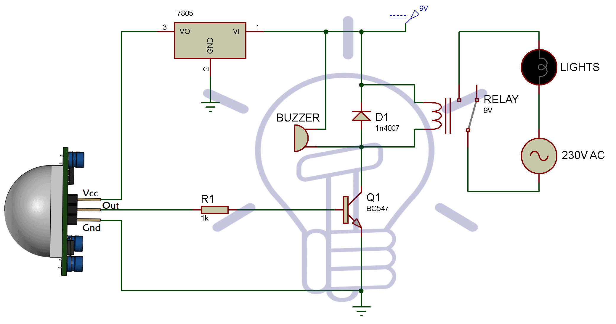
The bulb in the circuit can be replaced with any of the home appliances which works on 230V AC. Also, you can add a switch between the supply and input pin of the regulator, to manually turn ON and OFF the motion detector system.
Note: – PIR sensor only detect the presence of the infrared rays which comes into its range, it does not emit infrared.
Working of Motion Detector Circuit
The PIR sensor typically operates at 5V, so we are using a positive voltage regulator IC 7805, which will give 5V output to feed the sensor. Hence, the Vcc is connected with 3rd pin (Output Pin) of the 7805. The ground of PIR is connected with the ground terminal and the Output pin is connected to the base of the NPN transistor BC 547. Here, R1 is used as a current limiting resistor. The collector terminal of the transistor is connected with the 9V supply through a diode.
Here, a relay is used to control any electrical appliances, as we have connected light bulb with it. The buzzer is used here to notify whenever someone enters in the range of the PIR sensor.
So, as you start the power supply, the PIR comes into action. Initially, the output pin is at low, as no one is in the range of PIR sensor. So, the light bulb and the buzzer remain in off condition.
If there is any movement happen in the range of the PIR sensor, the output pin of the PIR goes HIGH. By which, the NPN transistor starts conducting current from collector to emitter. Therefore, it activates the relay and the buzzer connected with the collector terminal of the transistor. Hence, the light bulb starts glowing. The diode 1n4007 is used here to protect the relay from reverse current flow.
The relay and the buzzer get off automatically after a particular time duration set by the user.
Remove the alarm if you want to use the project as an automatic light system. Or remove the relay if you want to use the project as a motion detector circuit.
The main advantage of the circuit is, it can be used in night time also. Because the PIR detects the infrared rays emits from any object or the human body. PIR sensor has a wide area of detection. This is because of the Fresnel lens, which increases the PIR’s area of detection.
Also, PIR has two potentiometers, one is used for adjusting the sensitivity of the PIR sensor. And, the second one is used for adjusting the time delay for which the output of the PIR remains in HIGH condition.
Applications of Infrared Motion Detector and Sensor
There are a number of places where we can use a motion detector circuit. Some of them include-
- Motion detector also used for intruder alarms
- It can be used in malls and public places for automatic door opening
- In automatic toilet flusher
- It can be used in a basement or covered parking area to avoid the chance of accidents.
- Home-automation devices.
- It can be used at lift lobby and multi-apartment complexes for security purposes.
Bottom Line
From the above discussion, we can say that Motion detector circuit is easy to design and use. Now I am concluding the article with a discussion of working, circuit diagram, use and advantages of motion detector circuit and the components used in it. We hope that you have got a sound knowledge of motion detector Circuit, PIR sensor and it’s working. Now, you will be able to design this highly reliable and pocket-friendly “Motion detector circuit” with ease.
You may also read:


phenomenon work,brillaint