Design of Grounding / Earthing System in a Substation Grid
Design of Earthing / Grounding System in a Substation Grid
Introduction to Substation Earthing Grid
In high and medium voltage[1]Air Insulated Substations (AIS) the electromagnetic field, which causes are the static charges of bare cable and conductors and by the atmospheric conditions (surges), induce voltages at no-live parts of the installation that create potential differences between metallic parts and ground and also between different points of the ground.
Similar situations can occur when there are faults between live parts of the installation and no-live parts, for example in phase-to-earth short circuit.
These potential differences give origin to step potential and touch potential, or a combination of both, that can lead to circulation of an electric current through the human body, that can cause hazardous to people.
Touch voltage (Et) can be defined as the maximum potential difference that exists between an earthed metallic structure capable to be touched by the hand and any point of the ground, when a fault current flows.
It is usual to consider a distance of 1 m between the metallic structure and the point on the ground.
Step voltage (Es) is defined as the maximum potential difference that exists between the feet when a fault current flows.
It is usual to consider a distance of 1 m between the feet.
A particular case of step voltage is the Transferred voltage (Etrrd): where a voltage is transferred into or out of the substation from or to a remote point external to the substation site.
Other concepts are:
- Ground potential rise (GPR): The maximum electrical potential that a substation grounding grid may attain relative to a distant grounding point assumed to be at the potential of remote earth. This voltage, GPR, is equal to the maximum grid current times the grid resistance.
- Mesh voltage (Em): The maximum touch voltage within a mesh of a ground grid.
- Metal-to-metal touch voltage (Emm): The difference in potential between metallic objects or structures within the substation site that may be bridged by direct hand-to-hand or hand-to-feet contact.
The diagram in Figure 1 shows the phenomena referred above.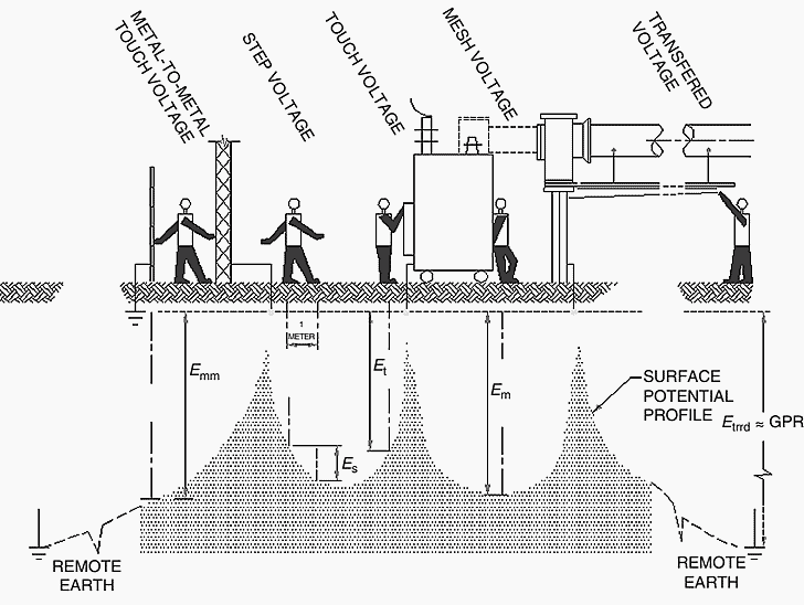
Figure 1 – Touch, step and transferred voltages
In order to minimize to acceptable values of the currents through the human body, to ensure electrical safety for people working within or near the installation, and also to limit any eventual electrical interference with third-party equipment, AIS must be provided with an earthing (or grounding) system, to which all metallic non-live parts of the installation must be connected, such as metallic structures, earthing switches, surge arresters, enclosures of switchboards and motors, transformers rails and metallic fences.
Since earthing has an influence on the levels of power system overvoltages and fault current, and the definition of protection systems, earthing system must be designed to ensure that there is proper operation of the protective devices such as protective relaying and surge arresters.
Design and construction of earthing system must assure that system performs for the expected life of the installation and it must therefore take into account future additions and the maximum fault current for the ultimate configuration.
Earthing system is made of a mesh of buried bare copper cable, with additional earth rods, and shall be calculated, being recommended to use IEEE Std. 80-2000.
- Related Post: Difference Between Grounding, Earthing and Bonding
Important formulas for Designing a Substation Grid Earthing System
The cross section of the buried cable should calculated in accordance with the value of the phase-to-earth short circuit current, but it is common to use the three phase short-circuit current for this purpose.
For this calculation the following formula must be used: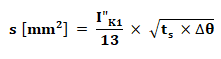 Where:
- I”K1 is the phase-to-earth short-circuit current [A]
- ts is the duration of the fault [s]
- Δθ is the maximum admissible temperature rise [°C] – for bare copper Δθ = 150 °C
According to the referred IEEE Standard maximum tolerable step and touch potential and maximum tolerable current through the human body (Ihb) and the resistance of the earth grid (Rg) are calculated by the formulas:
Maximum tolerable step potential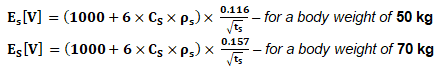
Maximum tolerable touch potential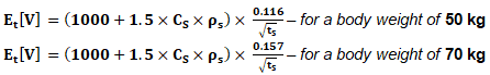
Maximum tolerable current through the human body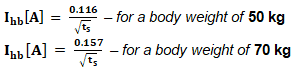
Resistance of the Earth Grid
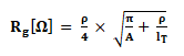
Where:
- Cs is the surface layer derating factor and is calculated by the formula:

- ts is the duration of the fault [s]
- ρs is the surface material resistivity [Ω.m] – typical value for wet crushed rock/gravel: 2,500 Ω.m
- ρ is the resistivity of the earth beneath the surface material [Ω.m]
- hs is the thickness of the surface material [m]
- A is the area occupied by the ground grid [m2]
- lT is the total buried length of conductor, including the earth rods [m]
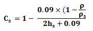
If no protective surface layer is used, then Cs =1 and ρs = ρ
These calculations are usually done using specific software.
Substation Earthing Grid
Figure 2 shows an example of the earth grid.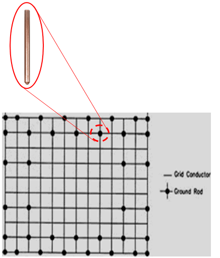
Figure 2 – Earth grid
The most suitable methods for the connection of the earth grid connections are:
a.) Exothermic welding
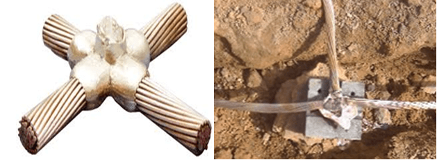
Figure 3 – Exothermic welding
Exothermic welding is conductors’ permanent connection process that uses molten metal and molds, which is based in a chemical reaction between metal oxides (the conductor) and ignited aluminium powder, which acts as fuel, with heat energy release. This chemical reaction is a pyrotechnic composition known as thermite.
It must be assured that the number of exothermic welding done with each mold will not exceed the indications of the manufacturer.
b.) C connector:
using a hydraulic crimping tool and matrixes with a size suitable for the size of the connectors.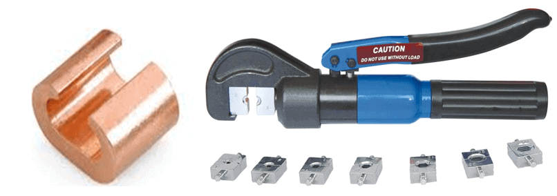
Figure 4 – C connector and crimping tool
Close to the control boxes of circuit breakers, switches and isolators it must be installed a metallic equipotential mat, connected to the earth system, similar to the one shown in Figure 5.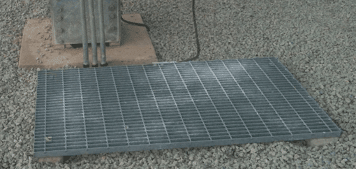
Figure 5 – Metallic equipotential mat
![]()
Related Posts:


Please senda me información about courses.
what is the min capacity of the substation that requires an earth grid installation ?
Thank you.