Phase Locked Loop- its Operation, Characteristics & Application
What is Phase Locked Loop? Its Concept of Working, Characteristics & Applications
What Is Phase Locked Loop?
The phase locked loop or PLL is an electronic circuit with a voltage controlled oscillator, whose output frequency is continuously adjusted according to the input signal’s frequency.
A Phase locked loop is used for tracking phase and frequency of the input signal. It is a very useful device for synchronous communication. PLL acquires the carrier frequency in suppressed carrier mode of communication and produces a coherent carrier signal inside the receiver for demodulation.

Block Diagram
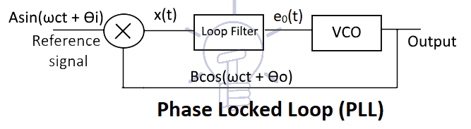
A PLL operates like a typical feedback system. It updates the output frequency of VCO until it matches the frequency of the input signal i.e. in sync with the input signal.
Concept Of Operation
The operation of Phase locked loop is based on the phase difference between the input and output signals. The phase difference between of two signals can be understood by the figures given below.

The figure above shows two sinusoidal signals having a constant phase difference. When two signals have constant phase difference then they are said to have the same frequency. They only have shifted phase. Thus it shows that the two signals are at the same frequency.

However, this figure shows two signals having a varying phase difference. This changing difference shows that the two signals are non-coherent. It means that the two signals are totally different signals with different frequencies.
It is clear from the discussion above that the phase difference is related to the frequency of the signal. The Phase locked loop makes the phase difference constant between its input & output signal. And produce a stable frequency signal same as the input signal.
This key concept is put to use in PLL device.
Related Post: Quantization & Sampling? Types & Laws of Compression
Operation Of Phase Locked Loop (PLL)
There are 3 components of PLL and the operation of each component is given below.
Voltage Controlled Oscillator (VCO)
The Voltage Controlled Oscillator often known as VCO is a type of oscillator that produces a sinusoidal signal whose frequency can be controlled by an external voltage. The frequency produced by VCO is varied linearly with respect to the input voltage. The sinusoidal output of the VCO is
ω(t) = ωc + c eo(t)
Where c is the constant of VCO & eo(t) is the voltage proportional to the phase difference between the input signal’s frequency and VCO’s frequency. ωc is the free running frequency of the oscillator.
The output of VCO is ωc if eo(t) = 0. However, if eo(t) is positive, then the output frequency of VCO will increase & if eo(t) is negative, then the output frequency will decrease.
Phase Detector
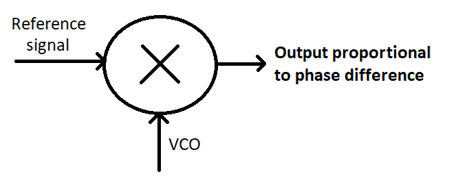
The phase detector is an electronic circuit that compares two signals and generates a voltage signal which is proportional to the phase difference between the two signals.
Basically, a phase detector is a multiplier. It multiplies the two sinusoidal signals i.e. the input/reference signal & the output of VCO.
Suppose the input signal is A sin(ωct+ϴi) & the output signal of VCO is B cos(ωct+ϴo)
Then the output of phase detector x(t) is:
x(t) = A sin(ωct+ϴi) B cos(ωct+ϴo)
x(t) = AB sin(ωct+ϴi) cos(ωct+ϴo)
x(t) = AB/2 {sin(ωct+ϴi+ ωct+ϴo)+ sin(ωct+ϴi– ωct-ϴo)}
x(t) = AB/2 {sin(2ωct+ϴi+ϴo)+ sin(ϴi-ϴo)}
x(t) = AB/2 sin(2ωct+ϴi+ϴo)+ AB/2 sin(ϴi-ϴo)
The high frequency component is then removed by using the loop filter discussed below.
3) Loop Filter
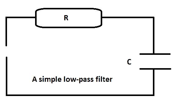
The filter used in the loop of PLL is a narrow band low pass filter. It filters any high-frequency components from the output signal of the phase detector and provides a fixed voltage signal to VCO.
After passing the signal x(t) through loop filter it blocks the term of high frequency.
x(t) = AB/2 sin(2ωct+ϴi+ϴo)+ AB/2 sin(ϴi-ϴo)
The output signal eo(t) of loop filter is
eo(t) = AB/2 sin(ϴi-ϴo)
Where AB=2 & (ϴi-ϴo) is the phase difference. If there is a non-zero phase difference, then the loop filter will produce a voltage signal proportional to the phase difference. Due to this voltage signal, the output of VCO is maintained.
How It Works
As long as there is a phase difference it will keep maintaining its frequency until it is locked. In such condition, both signals have same frequency & constant phase. These both signals are said to be phase coherent or in phase lock.
Suppose the PLL is locked & the VCO is generating a stable frequency. Suddenly the input signal’s frequency increases i.e. ωc+k
A sin((ωc +k)t+ϴi) = A sin(ωct+kt+ϴi)
Then the output of loop filter will be
eo(t) = AB/2 sin(kt+ϴi-ϴo)
This, in turn, increases the difference and the voltage output of loop filter increases. Due to which the frequency of the VCO output signal increase.
Characteristic Of PLL
- Phase-locked loops are designed for a Specific range of frequencies. This range of frequency is called Capture Range of PLL. A PLL can lock onto a signal if its frequency lies in its Capture Range.
- When the PLL is locked onto an input signal, the input signal can be changed. Suddenly, the input signal changes then the PLL will start tracking its phase and frequency in a fixed range. This tracking range is called Lock Range.
- The most important feature of PLL is the noise filtering. It completely blocks any unwanted low power frequencies from the input signal and provides a pure and stable sinusoidal wave.
Applications of PLL (Phase Locked Loop)
It is the most widely used circuit in modern communication.
- It is used in demodulation of Amplitude Modulated suppressed carrier signal.
- It is also used for demodulation of Frequency Modulated & Phase Modulated signals.
- It can also be used in clock recovery from a signal.
- Because of its stable nature, it is used as frequency synthesizer in almost every digital device.
- A crystal oscillator can generate stable frequency up to 300Mhz. while PLL can generate signals of a high & stable frequency greater than 300 Mhz.
- It is used in different devices such as a signal analyzer, signal generator, radar, cell phones & radio etc.
Related Post: Types of Modulation Techniques used in Communication Systems


Good