Types of Modulation Techniques used in Communication Systems
The Basic Modulation Concept: Baseband, Bandpass, Message, Carrier, Modulated Signal & Basics of Amplitude and Angle(FM, PM) Modulation
The Modulation Concept
The modulation concept comes into consideration when the signal needs to be transmitted over a long distance through an antenna. Antenna helps transmit the signal over long distance.
The modulation concept makes the communication purely wireless and mobile. And because of modulation, we can now roam freely without the fear of getting out of the communication grid.
Baseband Signal
A signal consisting of significantly lower frequency (up to 10 kHz) is known as a baseband signal. Example of the baseband signal is voice, audio and video signal.
The frequency range of voice signal is 300Hz to 3.5 kHz.
Audio signal’s frequency range is 20 Hz to 20 kHz.
Video signal’s frequency range is 0Hz to 4.5 MHz
All of these signals contain low frequencies (up to 10 kHz), which makes them baseband signals. The baseband signal cannot be transmitted directly through the antenna. Thus it gives rise to the concept of modulation.
Bandpass Signal
If a signal consists of significantly higher frequencies (Higher than 100 kHz) then it is known as Passband or BandPass signal. Bandpass signal does not contain any frequency lower than 100 kHz.
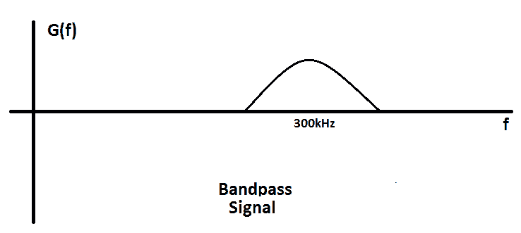
Bandpass signal can be directly transmitted through the antenna.
Using the process of modulation, the signal with low frequency, also known as Baseband signal is converted into a signal with high frequency, also known as Bandpass signal.
Message Signal:
The signal that is used in modulating the carrier signal during modulation is called the message signal.
The message signal is a baseband signal. for example, voice, sound, video, images & data signals are baseband signals.
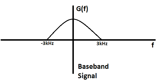
Suppose a baseband message signal m(t) is a rectangle signal with T = 1ms. To show its frequency spectrum, we need to do its Fourier transform.
We know that the Fourier transform of rectangle function is a sinc function but for the sake of understanding, we will just go with the spectrum given below. The spectrum of m(t) signal is given in the figure:
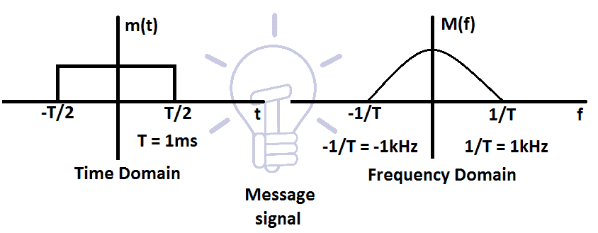
The frequency f of m(t) ranges from 0 to 1Khz, which makes it a baseband signal.
Related Post: Introduction to Signals, Types, Properties, Operation & Application
Carrier Signal
The sinusoidal signal with a much higher frequency that is used in the modulation is called the carrier signal.
Let’s suppose a carrier signal c(t), that is a sinusoidal signal with high frequency. And the frequency fc of the carrier signal is 300 kHz. The time domain figure and the Fourier transform of the carrier signal are given in the figure below:
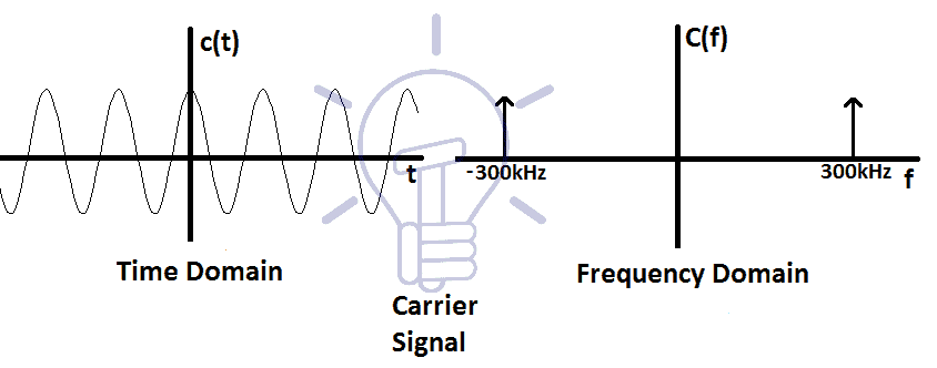
As you can see, the spectrum of carrier signal only contains the frequency 300 kHz. This makes it a bandpass signal. It is easily transmitted through the antenna.
We need to transmit the message signal m(t) with the help of the carrier signal c(t). To make it able to transmit through the antenna, we need to translate the message signal m(t) onto the carrier signal c(t).
Related Post: Quantization & Sampling? Types & Laws of Compression
Modulated Signal
The resultant signal acquired after modulation of message and carrier signal is called a modulated signal.
A simple modulated signal is acquired by the multiplication of carrier and message signal. The resultant signal is the modulated signal.
Suppose the product signal p(t) is the modulated signal of m(t) & c(t). It is a sinusoidal signal, where the amplitude of message signal m(t) is not 0. The time domain and frequency domain figures of modulated signals are given below:
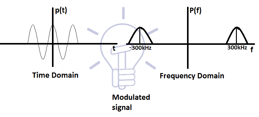
The modulated signals frequency is shifted by the frequency of the carrier signal fc. The spectrum shows 2 sides (negative and positive side)of the frequencies, which is nothing but a mirror of each other.
The modulated signal’s spectrum consists of lower and higher side. Lower and higher frequency is determined by (fc-f) and (fc+f) respectively.
This modulated signal is now a bandpass signal and an antenna can easily transmit it.
Related Post: What is GSM and How does it Work?
Modulation
The process in which one of the characteristic parameter (amplitude, frequency, phase) of the carrier signal varies linearly with respect to message signal’s amplitude is called modulation.
Types Of Modulation
Basic types of Modulation are defined with figures below.
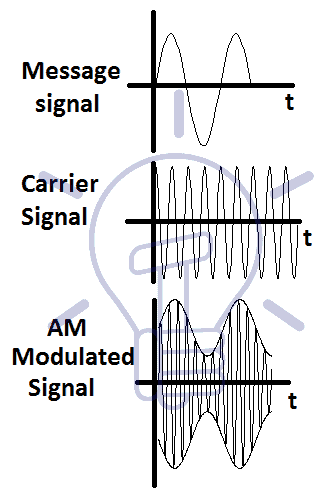
Amplitude Modulation (AM)
The type of modulation in which the amplitude of the carrier signal varies with respect to the amplitude of the message signal is called Amplitude Modulation.
The message signal’s information is stored in the amplitude (envelope) of the modulated signal.
Angle Modulation
The modulation which is based on changing the frequency or phase of the carrier signal with respect to message signal is called Angle modulation. Angle modulation comprises of frequency modulation & phase modulation.
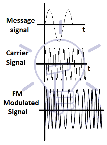
Frequency Modulation (FM)
The type of modulation in which the Frequency of the carrier signal varies with respect to the amplitude of the message signal is called Frequency modulation.
The message signal’s information is stored in the frequency of the modulated signal.
Phase Modulation (PM)
The type of modulation in which the phase of the carrier signal varies linearly with respect to the amplitude of the message signal or data signal is called Phase modulation.
The information of the message signal is stored in the phase of the modulated signal.
- Related Post: What are Industrial Communication Networks? An Overview