Modulation – Classification and Types of Analog Modulation
What Is Modulation? Analog Modulation & Its Types i.e. Amplitude, Frequency & Phase Modulation
What is Modulation?
The process of varying any of the three characteristics as the Amplitude, Frequency or the Phase of a carrier signal is called as modulation
We know that the information signal to be transmitted can be of any form such as data, music, video etc. But before transmission, it is converted into its equivalent electrical form. The electrical equivalent form of the original signal is called the baseband signal.
Every electrical signal possesses basic characteristics such as Amplitude, Frequency, and Phase. We need to change the characteristics of the signal to make it more appropriate for the transmission.
Need of Modulation
We need modulation because of the following reasons:
- It reduces the height of the antenna used for the transmission.
- It increases the range of communication.
- Using Modulation avoids the mixing of the signal.
- Modulation makes multiplexing of the signal possible.
Related Post: Types of Amplitude Modulation (AM) – Advantages & Disadvantages
Block Diagram of Modulation
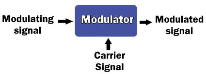
This block diagram shows a modulator with two inputs i.e. modulating signal and carrier signal. And at the output, we get the modulated signal.
The modulating signal is nothing but the information signal. This modulating signal is primarily of two forms such as analog signal and digital signal. The design of the modulator depends on the input signal’s
The carrier signal is the signal upon which the modulating signal is modulated. This carrier signal is a sinosoidal signal of a fixed frequency known as the carrier frequency, which is very comparatively very higher than the modulating signal.
The modulated signal is the resultant output signal of the modulator.
- Related Post: The Modulation Concept & Basic Types of Modulation
Types Of Modulation
Modulation is divided into two types;
- Analog Modulation
- Digital modulation
Analog modulation is further divided into three types;
- Amplitude modulation
- Frequency modulation
- Phase modulation
Whereas, Digital modulation is further divided into three types;
- Pulse Amplitude modulation (PAM)
- Pulse width modulation (PWM)
- Pulse code modulation (PCM)
In this article, we will cover Analog modulation and its types.
Analog Modulation
Analog modulation deals with an analog signal. The types of analog modulation are briefly discussed below.
Amplitude Modulation
Amplitude modulation is a type of analog modulation in which the amplitude of the high-frequency carrier signal is changing with respect to the instantaneous amplitude of the modulating signal.
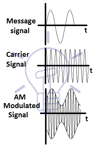
In amplitude modulation, the amplitude of the carrier signal changes instantaneously with respect to the amplitude of the modulating signal. However, the frequency and the phase of the carrier signal remains constant. Thus the information is contained in the amplitude of the carrier signal.
- Related Post: Quantization & Sampling? Types & Laws of Compression
Mathematical Representation
Suppose the modulating signal is a sinusoidal signal, it can be represented as:
m(t) = Am cos ωmt
where:
m(t) = instantaneous amplitude of the modulating signal
Am = Peak amplitude of the modulating signal
ωm = 2πfm
fm = Frequency of modulating signal
Similarly, the carrier signal is represented as;
c(t) = Ac cos ωc t
Where:
Ac = Peak amplitude of the carrier signal
ωc = 2πfc
fc = Frequency of carrier signal
The Amplitude modulated wave is represented as:
mam(t) = Aam cos ωc t
Where;
Aam is the instantaneous amplitude of the envelope of the modulated signal. So it is represented as
Aam = Ac + m(t)
Aam = Ac + Am cos ωmt
Substituting Aam into mam(t),
mam(t) = (Ac + Am cos ωmt) cos ωc t
mam(t) = Ac (1 + (Am/Ac) cos ωmt) cos ωc t
Where the modulation index is;
μ = Am/Ac
Thus
mam(t) = Ac (1 + μ cos ωmt) cos ωc t
Modulation index μ should be between 0 to 1 for envelope detection during demodulation.
- Related Post: What is GSM and How does it Work?
Frequency Spectrum
The representation of frequency content of a signal using a graph is called spectrum.
The mathematical equation of AM modulated wave;
mam(t) = (Ac + Am cos ωmt) cos ωc t
mam(t) = Ac cos ωc t + Am cos ωmt cos ωc t
Using trigonometric identity 2 cos A cos B = cos (A+B) + cos (A-B)
mam(t) = Ac cos ωc t + (Am/2) cos (ωm + ωc )t + (Am/2) cos (ωm – ωc )t
Where:
Ac cos ωc t = Carrier signal
(Am/2) cos (ωm + ωc )t = Message spectrum shifted ωc to the left.
(Am/2) cos (ωm – ωc )t = Message spectrum shifted ωc to the right.
Thus we get the spectrum of AM as follows;
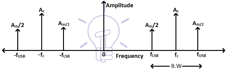
Where the bandwidth of the signal is the difference between FLSB and FUSB.
Bandwidth = FLSB – FUSB
Bandwidth = (fc – fm) – (fc + fm)
Bandwidth = 2fm
AM Transmitter
The basic components of AM transmitters are oscillator and power amplifier.
Oscillator
The oscillator is a circuit which generates sinusoidal waveforms of different frequencies. The crystal oscillator is generally used in AM transmitter for generating a carrier signal of high frequency.
Power Amplifier
Power amplifiers are used for the amplification of the modulated signal before feeding it to the antenna for transmission. The modulated signal has low power and it cannot be transmitted without amplification.
Bipolar junction transistors are used as Power amplifiers in AM transmitter.
There are 3 classes of Power Amplifiers.
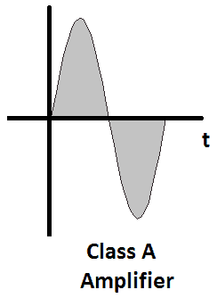
Class A Power Amplifier
The class A amplifier operates for the whole cycles of the signal. These amplifiers amplify the whole signal thus wasting too much power. Class A amplifier has low efficiency.
Class B Power Amplifier
Class B amplifiers operate only for half of the input signal thus the efficiency of the Class B amplifiers ranges up to 80%.

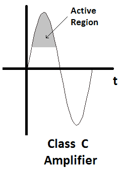
Class C Power Amplifier
While Class C amplifiers only operate for only 25% (positive high portion) of the signal. Thus the efficiency of class C amplifiers is 90%.
There are 2 types of AM transmitters
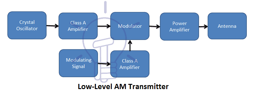
Low-Level AM Transmitter
In the low-level transmitter, a crystal oscillator is used for generating the carrier signal. The carrier and modulating signal is amplified using class A amplifier before modulation. After modulation, the modulated signal is amplified again before transmission.
The low-level transmitter does not need high-efficiency Amplifiers thus its design is much simpler.
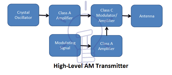
High-Level AM Transmitter
The high-level transmitter has the same design as low-level transmitter except it uses Class C amplifier at modulation stage. Because of class C amplifier, this transmitter has high efficiency and complex design.
In the High-level transmitter, the carrier signal and modulating signal is amplified using linear amplifiers. At the modulation block, both signals are amplified with modulation and then fed to the antenna for transmission. Block diagram of the High-level transmitter is as follows.
Advantages of AM
- AM transmitters have a simple design.
- AM receivers are also simple. Envelope detectors are the simplest receivers.
- Due to high power, AM signals have a long range of transmission.
- The AM signal has low Bandwidth.
Disadvantages of AM
- Because the information is stored in the amplitude of the modulated signal, which is affected by the noise in the medium.
- AM need high power for its transmission.
Applications of AM
- Because of its long range, it can be used for Radio broadcasting.
- It can be used for Television broadcasting.
Related Post: What are Industrial Communication Networks? An Overview
Frequency Modulation (FM)
In frequency modulation, the frequency of the carrier signal varies with respect to the instantaneous amplitude of the modulating (message) signal.
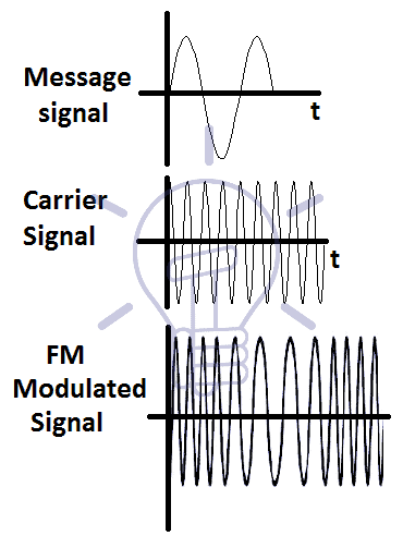
The amplitude and phase of the carrier signal remain unchanged. Only frequency of the carrier signal changes. Thus the information is stored in the frequency of the FM modulated signal.
The frequency of the carrier signal increases with an increase in the amplitude of the modulating signal and it decreases with the decrease in the amplitude of the modulating signal.
Frequency Deviation
The difference between the original frequency of the carrier signal and modulated frequency is called frequency deviation.
It is directly proportional to the amplitude of the modulating signal.
Consider the FM modulating signal to be a sinusoidal signal.
m(t) = Am cos(2πfmt)
The carrier signal is represented as:
c(t) = Ac cos (2πfct)
the instantaneous frequency of the modulated signal is:
fi(t) = fc + Kf m(t) Kf = constant
fi(t) = fc + Kf Am cos(2πfmt)
fi(t) = fc + δf cos(2πfmt)
Where:
δf = Kf Am = maximum frequency deviation
The minimum and maximum frequency of the FM modulated signal is:
Fmin = fc – δf
Fmax = fc + δf
And the bandwidth of the FM modulated signal is:
B.W = 2 fc x number of side-bands
B.W = 2 (fc + δ) Carson’s Rule
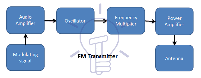
FM Transmitter
In FM transmitter the modulating signal is mixed directly with the high frequency carrier signal.
A general block diagram of FM transmitter is given below:
Advantages
- FM modulated signal is immune to noise as noise only affects the amplitude of the signal. And the information is stored in the frequency of the signal.
- FM signal consumes less power as compared to the AM signal.
- The transmitted power remains constant as the amplitude of the signal remains constant.
- Due to high frequency, the antenna of FM receiver is very small.
Disadvantages
- FM signal covers large bandwidth as compared to the AM signal.
- The design of FM transmitters and receivers are very complex.
Applications: - FM can be used for radio broadcasting.
Types of Control and Communication Cables
Phase Modulation
The process in which the phase of the carrier signal varies with the instantaneous amplitude of the modulating (message) signal is called phase modulation.
Mathematical Representation
Consider the message signal is a sinusoidal signal.
m(t) = Am cos(ωmt)
The carrier signal is a high-frequency sinusoidal signal.
c(t) = Ac cos(ωct + ϴ)
ϴ is the phase of the signal and normally it is zero.
The Phase modulated signal is given below:
ϕpm(t) = Ac cos(ωct + ϴ + Kp m(t))
ϕpm(t) = Ac cos(ωct + ϴ + Kp Am cos(ωmt))
Kp = constant of proportionality for phase modulation.
The instantaneous frequency of PM signal is;
ωi = d/dt (ωct + ϴ + Kpm(t))
ωi = {ωc+ Kp d/dt(m(t)}
The equation of the instantaneous frequency shows that in PM the derivative of modulating signal is added with the frequency of the carrier signal.
Thus it proves that if we take the derivative of the modulating signal before feeding it to Frequency modulator we get Phase modulation.
Phase Deviation
Phase deviation is the maximum difference between the original phase of the carrier signal and the modulated signal. The equation of phase modulated signal is;
ϕpm(t) = Ac cos(ωct + ϴ + Kpm(t))
Substituting m(t)
ϕpm(t) = Ac cos(ωct + ϴ + Kp Am cos(ωmt))
ϕpm(t) = Ac cos(ωct + ϴ + δp cos(ωmt))
Where δp = KpAm = maximum phase deviation
Phase modulation has same properties as Frequency modulation, that is why they have same advantages and disadvantages.
Submarine Cables – Construction, Characteristics, Cables Laying & Joints


