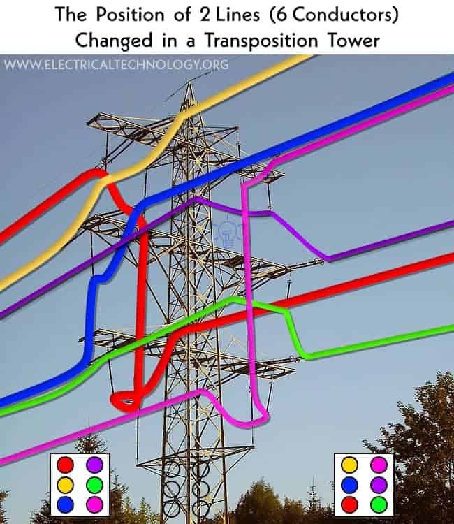
Why are Overhead Conductor Positions Exchanged in a Transposition Tower?
Electrical energy is transmitted in high-voltage three-phase lines without a neutral (3 conductors). Over long distances, these lines develop reactances, both inductive and capacitive, between each other and between the conductors and the ground. To counteract the effects of these reactances, transpositions are made, which involve reversing the positions of the phases. Transposition towers are typically used for this purpose.
Click image or open in a new tab to enlarge

What is Transposition in Transmission Lines?
Transposition in power lines refers to the practice of intentionally crossing over or twisting the positions of conductors within a transmission line. This technique is primarily used in high-voltage power lines, especially those operating at frequencies above 60 Hz. Transposition is done to reduce the electromagnetic interference (EMI) and radio frequency interference (RFI) that can be generated by the conductors.
Transposition is defined as the periodic swapping of positions of transmission line conductors to improve the efficiency of power transmission system. The pole or tower used to exchange the phase conductors over it is known as a transposition tower or pole.
By transposing the positions of the conductors, the overall symmetry of the line is improved, which helps in canceling out some of the electromagnetic fields that can be emitted by the conductors. This, in turn, reduces the potential for interference with nearby communication systems and improves the overall efficiency and reliability of the power transmission line.
Why and How is Swapping of the Conductors Done in Overhead Power Lines?
Transposition is typically done by periodically swapping the positions of the conductors along the length of the transmission line. This can be done using specialized equipment and techniques to ensure that the conductors are properly aligned and insulated to maintain the integrity of the power transmission system.
When all three conductors of a power transmission line are placed evenly like the corners of an equilateral triangle, it’s called symmetrical spacing. (as shown in below fig).
In the case of symmetrical spacing:
d = d1 = d2 = d3
Here, the flux linkage and inductances of each phase have same expression. Hence, the power flow in overall power system is smooth.
However, in most practical cases, 3-phase line conductors are not equidistant from each other. For such cases, the conductor spacing is said to be unsymmetrical (example shown here).

Under such conditions, the flux linkage and inductances of each phase are not the same. Even if the currents are balanced, the different inductances in each phase result in unequal voltage drops in the three phases.
As a result of this, the voltage at the receiving end will not be the same for all phases. Hence, power flow can be uneven.
To introduce some voltage drops in all conductors, the positions of the conductors are interchanged at regular intervals along the line so that each conductor covers an equal distance. Technically, this interchange is described as transposition.
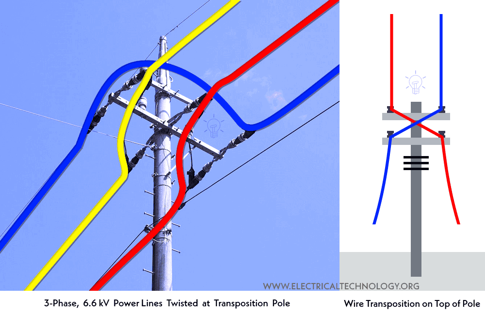
Transposition is practically carried out on a special-purpose tower named a transposition tower.
The figure below shows an example transposition of 3-Phase, Two-lines having 6 conductors. The color coded blocks shows the conductors position before and after the transposition. In the example image, we can see how two lines (6 conductors in total) arrive and how the position of all of them changes. Consider the conductors on the left side of the pole. Here, we will be using color coding for ease of identification.
The fig below displays poles for three phase (3-lines) and 2 conductors for transposition purposes.
The main purpose of transposition in a transmission line is to reduce the mutual coupling between conductors. It also helps to minimize the overall level of interference. This is particularly important in multi-phase AC transmission lines. Transposition helps to achieve electrical symmetry in the line, which can lead to several benefits:
- Reduced Electromagnetic Interference: Transposition reduces the level of electromagnetic interference between adjacent conductors. It is used to improve the overall efficiency and performance of the transmission line.
- Improved Balance: By exchanging the positions of the conductors, transposition helps to achieve a more balanced distribution of currents in each phase. This can reduce losses and improve the efficiency of the line.
- Mitigation of Inductive Effects: Transposition helps to mitigate the effects of inductive coupling between the conductors. These effects causes unwanted voltage drops and power losses.
- Improved Line Stability: Transposition can help improve the stability of the transmission line by reducing the likelihood of voltage fluctuations and other disturbances.
Related Resources and Interesting but informative Questions and Answers Related to Power System
- Will a Man Get an Electric Shock If He Hangs on a Live Wire?
- How Does Temperature Impact Sag in Overhead Lines?
- What is the Minimum Ground Clearance for Overhead Power Line?
- What is the Power Angle in a Power Transmission Line?
- Why are Overhead Power Lines Loose on Electric Poles & Towers?
- How Many Poles and Towers are Situated Within a 1-km Span?
- Why are Overhead Power Transmission Lines Not Insulated?
- Why Don’t Birds and Squirrels Get Electrocuted on Power Lines?
- Skin Effect and Factors Affecting Skin Effect in Power Lines
- Ferranti Effect in Power Lines – Causes, Advantages & Disadvantages
- Corona Effect & Discharge in Transmission Lines & Power System
- What is the Purpose of Ground Wire in Overhead Transmission Lines?
- Why is the Grounding Wire Bare and Not Insulated?
- Why is Power Transmitted at High Voltage Instead of High Current?
- Why is the Ground Wire Always Positioned Above the Overhead Power Lines?
-
 Why are Inductive & Capacitive Reactances Measured in Ohms?
-
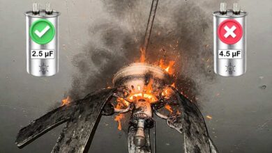 What Happens If You Install a Larger Capacitor in a Fan?
-
 Robotic Snakes that Crawl Power Lines to Detect Faults
-
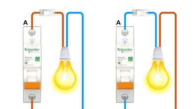 Can You Install Breakers and Switches on Neutral Conductor
-
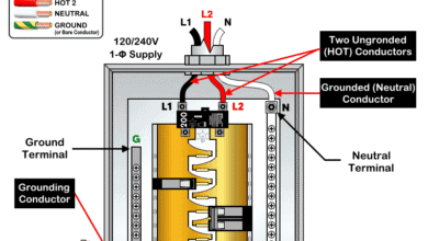 Difference Between Grounding, Grounded and Ungrounded Conductors
-
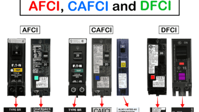 Difference Between AFCI, CAFCI, DFCI and GFCI?