How a Distribution Transformer Steps Down 11kV to 230V and 400V (1-Phase and 3-Phase)
What is a Distribution Transformer
A distribution transformer (also called a pole-mounted, pad-mounted, or ground-mounted transformer) is a step-down transformer used in electrical distribution systems to reduce medium voltage (such as 11kV to 13.2kV) to low voltage levels (such as 400/230V) for consumer use.
It is the final voltage-transforming device in the power distribution network that supplies electricity to residential, commercial and industrial applications. It distributes and provides single phase and three phase power supply to the final consumer units.
In a typical power system, distribution transformers are connected from the substation via primary distribution of 11kV. At distribution transformer, it step-down the 11kV voltage to 400V three phase and 230V single phase. The 400/230V is supplied via secondary distribution to the final consumer i.e. homes, shops, offices, and small industries.
- Related Posts: Difference Between Power and Distribution Transformer
Now, let’s know the the working and operation of the unsung heroes that power our lives with energy and light.
Working Principle of the Distribution Transformer
A distribution transformer works on the principle of electromagnetic induction (Faraday’s Law). It has two windings wrapped around a laminated steel core:
- Primary winding
- Secondary winding
Primary Winding
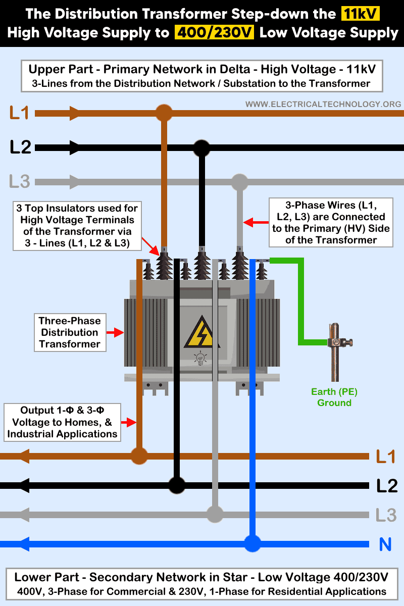
The primary winding of the transformer is connected to the 11kV supply in a Delta (Δ) configuration. The upper section (i.e., the primary network) receives the 11kV high-voltage input through three phase lines from the distribution network or substation.
The three phase conductors (L1, L2, and L3) are terminated at the high-voltage (HV) side of the transformer. For this connection, three top-mounted insulators are used to support and isolate the HV terminals. These high voltage terminals are used for three incoming lines (L1, L2, and L3) to be safely connected to the primary winding.
Good to Know: The primary side of a distribution transformer is a 3-phase, 3-wire (3P, 3W) system. In other words, it uses a delta (Δ) connection and therefore does not have a neutral conductor.
Secondary Winding
The secondary winding of the transformer supply both 400-415 three phase and 230V single phase supply in Star (Y or Wye) configuration. The lower part (i.e., secondary network) carries low voltage of 400/230V (3-Φ and 1-Φ). 400-415V is three phase power supply for commercial while 230V is 1-phase for residential applications.
The three phase conductors (L1, L2, and L3) and a Neutral are terminated at the low-voltage (LV) side of the transformer. For this connection, four mounted insulators are used to support and isolate the LV terminals. These low voltage terminals are used for four outgoing lines (3Lines + 1N) to be safely connected to the secondary winding.
The secondary side of the distribution transformer is a 3-phase, 4-wire (3P, 4W) system. In this arrangement, the fourth conductor is the neutral. In the figure, the lower conductor as neutral is shown in blue, while the upper three phase conductors are shown in brown, black, and grey according to the IEC color code. In older UK color codes, black was used for neutral, and red, yellow, and blue (R, Y, B) were used for the phase conductors.
As the secondary of the distribution is in star connection, the neutral is bonded (electrically connected) to the Neutral at the transformer.
Good to Know: Because the secondary winding of the distribution transformer is connected in a star (Y) configuration, the neutral point (star point) is bonded (i.e., electrically connected) to the neutral terminal at the transformer.
Click image or open in a new tab to enlarge
How the Voltage is Stepped Down
A distribution transformer reduces the 11 kV to the 400/230V as follow:
11 kV AC is applied to the primary winding. This high voltage creates an alternating magnetic flux in the transformer core. The magnetic flux links the secondary winding. Due to electromagnetic induction, the secondary winding produces a reduced voltage. The reduction depends on the turns ratio (N1/N2):
V1/N2 = N1/N2
For example:
- Primary voltage: 11,000V
- Secondary voltage: 400V
11,000/400
= 27.5
So the primary winding has ~27.5 times more turns than the secondary.
In simple words:
- Power comes from the substation at medium voltage (11kV).
- The 11 kV line connects to the primary of the distribution transformer.
- Magnetic coupling transfers energy to the secondary windings.
- The secondary outputs 400V – 3Φ or 230V – 1Φ.
- Low-voltage distribution lines carry the final voltage to consumers.
Related Post: Difference Between Single Phase and Three Phase Transformer
Voltage Levels in Distribution Transformer
400V – Three Phase & 230V – Single Phase
A typical three-phase distribution transformer outputs:
- 400V (Line-to-Line) – 3-Lines
- 230V (Line-to-Neutral) – 1 Line + Neutral
Click image or open in a new tab to enlarge
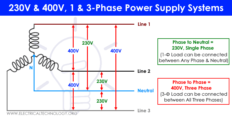
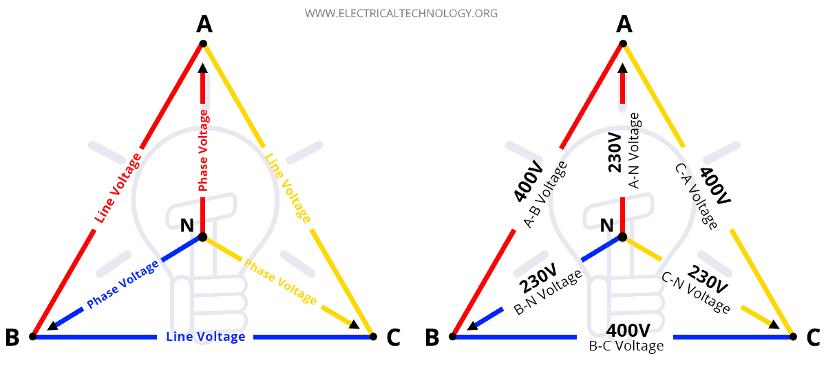
Three phase voltage is equal to the line voltage VL (400V) times 1.732 (√3)
Line Voltage (VL) = √3 × Phase Voltage
= √3 × 230V = 398 ≈ 400V
Therefore, Three Phase Voltage = 400V (Line to Line or Phase to Phase).
Similarly, Single phase voltage is equal to the line voltage VL (400V) divide by 1.732 (√3)
Phase Voltage (VPH) = Line Voltage ÷ √3
= 400V ÷ √3 ≈ 230V
Hence, Single Phase Voltage = 230V (Phase to Neutral).
Note:
- The Voltage between two lines (or phases) is known as Line Voltage (VL)
- Voltage between Phase and Neutral is known as Phase Voltage (VPH).
Click image or open in a new tab to enlarge
400V is suitable for three-phase motors, Industrial loads and commercial buildings which requires heavy-duty machineries and equipment.
Homes typically use 230V from any phase to neutral (Phase + Neutral + Earth) for lights, fans, small appliances and general sockets and outlets.
Related Posts:
- Transformer – Construction, Working, Types and Applications
- Different Types of Transformers and their Applications
- Applications of Electrical Transformer
- Difference Between Ideal and Real or Practical Transformer
- Difference Between Current Transformer & Potential Transformer
- Difference between AC and DC Transmission System & Power Lines
- Differences Between HVAC and HVDC & Power Transmission
- Advantages and Disadvantages of 3-Phase Transformer over 1-Phase Transformer.
- Advantages of HVDC over HVAC Power Transmission
- Why Electric Power Transmission is Multiple of 11 i.e 11kV, 22kV, 66kV etc?
- Corona Effect & Discharge in Transmission Lines & Power System
- Differences Between HVAC and HVDC & Power Transmission
- Can We Operate a 60Hz Transformer on 50Hz Supply Source and Vice Versa?
- Which Transformer is More Efficient When Operates on 50Hz or 60Hz?
-
 How to Wire 120/240V Smart Load Center with Smart Breakers
-
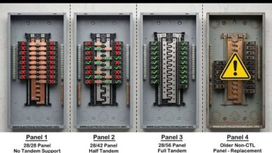
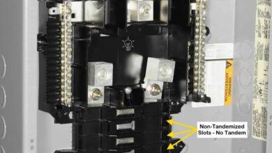 Difference Between CTL and Non-CTL Breakers & Load Centers
-
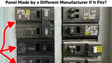 Can I Use a Different Brand Breaker in a Panel if it Fits?
-
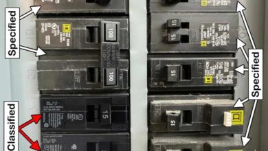 Difference Between Specified & Classified Circuit Breakers
-
 What is the Max Number of Breakers Allowed in a Main Panel?
-
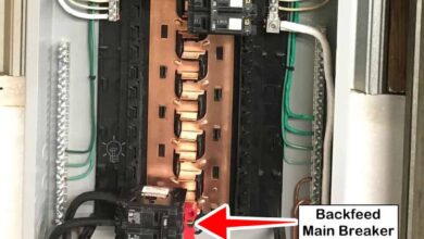 What is a Backfeed Main Breaker in an Electric Panel?