Electric Power System – Generation, Transmission & Distribution of Electricity
Typical Electric Power Supply Systems Scheme (Generation, Transmission & Distribution of Electrical Energy) & Elements of Distribution System
What is an Electric Power System?
An electric power system or electric grid is known as a large network of power generating plants which connected to the consumer loads.
As, it is well known that “Energy cannot be created nor be destroyed but can only be converted from one form of energy to another form of energy”. Electrical energy is a form of energy where we transfer this energy in the form of flow of electron. So, electrical energy is obtained by converting various other forms of energy. Historically, we have done it from chemical energy using cells or batteries.
Related Posts:
- Classification of Electric Power Distribution Network Systems
- Why Electric Power Transmission is Multiple of 11 i.e 11kV, 22kV, 66kV etc?
However, as the invention of generator had occurred, it became the technique to first convert some form of energy into mechanical form of energy and then converting it into electrical form of energy using generator. Generators produce two type of power AC and DC. Nevertheless, 99% of the present power systems use AC generators.
Electrical energy has grown immensely over two centuries because the flexibility it provides for its use. The variety of use has led its demand to increase monotonously. However, as the load or demand has increased practically one requirement is consistent. That is, we must generate the amount required by the load at that very instant because this large amount cannot be stored for delivering this high amount of demand.
Therefore, the generation of electrical energy is happening simultaneously as we use it. In addition, our demand is always varying. Therefore, the generation is also varying with it. Apart from varying demand, the type of current we consume also varies. These variations put many constraints and conditions. This is the reason of the complex and big control rooms across the whole power system.
The lines network between Generating Station (Power Station) and consumer of electric power can be divided into two parts.
- Transmission System
- Distribution System
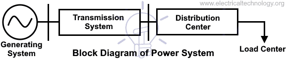
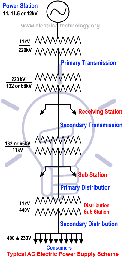
We can explore these systems in more categories such as primary transmission and secondary transmission as well as primary distribution and secondary distribution. This is shown in the fig 1 below (one line or single line diagram of typical AC power systems scheme).
It is not necessary that the entire steps which are sown in the blow fig 1 must be included in the other power schemes. There may be difference. For example, there is no secondary transmission in many schemes, in other (small) schemes of power system, there is no power transmission, but only distribution.
The main objective of an electric power system is to obtain electrical energy and make it reachable safely to the load point where it is being used in usable form. This is done in five stages namely
- Generating Station
- Primary Transmission
- Secondary Transmission
- Primary Distribution
- Secondary Distribution
The following parts of a typical power supply scheme are shown in figure 1.
After these five levels, the energy must be available as the stated form in terms of voltage magnitudes, frequency and consistency. Generation means the conversion of a form of energy into electrical energy. Transmission implies the transport of this energy to very long distance with very high amount of voltage magnitude. Moreover, distribution is fulfilling the demand of the consumers at certified voltage level and it is done in terms of feeders. Feeders are the small-small chunks of load distributed at different places, physically.
Related Posts:
- What Exactly Is A Smart Grid? Smart Grid Applications
- Integration of Renewable Energy with Grid System
Let’s explain all of the above levels one by one.
Generation or Generating Station
The place where electric power produced by the parallel connected three phase alternators/generators is called Generating Station (i.e. power plant).
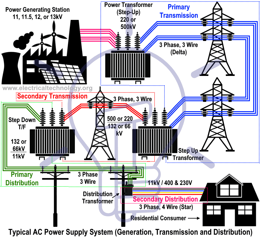
The ordinary power plant capacity and generating voltage may be 11kV, 11.5 kV 12kV or 13kV. But economically, it is good to step up the produced voltage from (11kV, 11.5kV Or 12 kV) to 132kV, 220kV or 500kV or more (in some countries, up to 1500kV) by Step up transformer (power Transformer).
Generation is the part of power system where we convert some form of energy into electrical energy. This is the source of energy in the power system. It keeps running all the time. It generates power at different voltage and power levels depending upon the type of station and the generators used. The maximum number of generators generate the power at voltage level around 11kV-20kV. The increased voltage level leads to greater size of generator required and hence the cost involved.
Presently the generating stations we employ mainly over the world are following:-
- Thermal power plant
- Hydel power plant (Hydro-electric)
- Nuclear power plant
- Diesel power plant
- Gas power plant
- Solar power plant
- Tidal power plant
- Wind power plant. Etc
- Related Post: Why Power Plant Capacity Rated in MW and not in MVA?
We generate electric energy through these power plants at different voltage levels and at different locations depending upon the type of the plant. They are used for different purposes viz.
- Base load plant:- When the plant is used to handle the base load demand on the system
- Peak load plant:- When the plant is made to handle the peak load demand on the system
Accordingly, the plant is made to handle the load. This categorization is important for the quality of power is being developed. It is also important for the fact that the power must be generated at the same instant when the load is taking up the power. So, as we know the type of load and approximate amount of load at the station, different type of generating station is chosen.
For example; Thermal plant, Hydel plant, Nuclear plant, Solar plant, Wind plant and Tidal plant are chosen to handle the base load on the system whereas Gas plants, Diesel plants are used to handle peak load demand. This is mainly governed by the nature of the time they take in the process of starting the delivery of power. Base load plants take more time in delivering the power whereas peak load plants must start very fast to supply the demand.
Related Post: Why Power Transmission Cables & Lines are Loose on Electric Poles & Transmission Towers?
Primary Transmission
The electric supply (in 132kV, 220 kV, 500kV or greater) is transmitted to load center by three phase three wire (3 Phase – 3 Wires also known as Delta connection) overhead transmission system.
As the voltage level which is generated is around (11-20) kV and the demand is at various levels of voltage and at very far away places from the generating station. For example, the generating station can be generating voltage at 11kv, but the load center is 1000km apart and at the level of 440V.
Therefore, for the delivery of electrical energy at such a long distance, an arrangement must be there to make it possible. Hence, the transmission system is essential for the delivery of electrical energy. This is made possible by using the transmission lines of different length. These are overhead transmission lines in almost every cases. Some exceptions occur when it is needed to cross an ocean. Then there is a compulsion to use underground cables.
But, as the system grew and load demand increased, the challenge in this process has become very complex. At low voltage level, the amount of current flowing through the line for high load demand is more and hence the voltage drop due to the resistance and reactance of the transmission line is very significant. This leads to more losses in the transmission lines and the decrease in the voltage at the load end.
- Related Post: Busbars and Connectors in HV and EHV installations
This affects the cost of the system and the working of the equipment the consumers use. So, transformer is used to increase the voltage level at certain values ranging from 220kV to 765kV. This makes the current value lesser for the same load that would be having higher values of current at certain load. The current value can be calculated using formula:-
![]()
Where, = RMS value of line to line voltage
= RMS value of line current
* denotes the conjugate of a phasor.
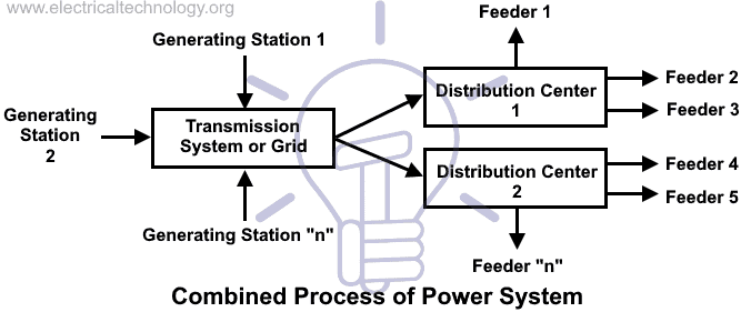
The increased demand and the constraint of location of generating station has made possible the need of a very complex system called ‘Grid’. This system connects multiple generating stations generating voltage at different levels being connected together as a combined system.
This makes the system to reach out to various load centers and this provides a great system of having higher reliability. Presently, this system has grown to size of a country. One more system is being used now a days is the use of HVDC. HVDC is used for greater distances and sometimes used to connect two grids of different voltage or frequency levels. HVDC also provides lower corona losses, lower communication interferences, elimination of inductive effect and elimination of frequency of operation.
Transmission lines vary in sizes. This size determines its characteristics and its behavior in the system. For example, in long transmission lines the voltage at the consumer end becomes higher than its rated value during light load condition due to the dominating capacitive nature of the transmission lines.
- Related Post: Is Reactive Power Useful? Importance of Reactive Power
Secondary Transmission
Area far from the city (outskirts) which have connected with receiving stations by lines is called secondary transmission. At receiving station, the level of voltage reduced by step-down transformers up to 132kV, 66 or 33 kV, and electric power is transferred by three phase three wire (3 Phase – 3 Wires) overhead system to different sub stations.
- Related Article: Electrical Transmission Networks – EHV and HV Overhead Lines
Primary Distribution
At a sub station, the level of secondary transmission voltage (132kV, 66 or 33 kV) reduced to 11kV by step down transforms.
Generally, electric supply is provided to those heavy load consumer (commercial power supply for inductries) where the demands is 11 kV, from the lines which caries 11kV ( in three phase three wire overhead system) and they make a separate sub station to control and utilize the heavy power in industries and factories.
In other cases for heavier load consumers (at large scale), the demand is upto132 kV or 33 kV. So electric supply provided them directly by secondary transmission or primary distribution (in 132 kV, 66kV or 33kV) and then step down the level of voltage by step-down transformers in their own sub station for utilization ( i.e. for electric traction etc).
When the transmission lines get closer to the demand centers, the voltage level is reduced to make it practical to distribute at different places of load. Therefore, power is taken from the grid and stepped down to 30-33kV, depending upon the places where it is being delivered. This is then transmitted to substations. For example, the system voltage at substation level in India is 33KV.
Related Posts:
- Failures In Electrical Systems, Equipments & Materials
- All About Electrical Protection Systems, Devices And Units
Many control mechanisms are provided in the substations to make the power delivery a controlled and continuous process without much disturbance. These substations deliver power to smaller units called ‘Feeders’. This is done by either ‘Overhead lines’ or ‘Underground cables’. These feeders are in towns, cities, or villages or it may be some group of industries, which takes the power from the substation, and convert its voltage level according to its own use.
For domestic use, the voltage is further reduced at 110V-230V (phase to ground) to be used by the individuals at different power factor. The combined amount of demand is the load on the entire system and that must be generated at that instant.
Depending upon the scheme of the distribution system, it is categorized as radial or ring mains. It gives different degree of reliability and stability to the system. All these systems are protected using various protection schemes comprising of circuit breakers, relays, lightening arresters, ground wires etc.
Many measuring and sensing elements are also associated like ‘Current transformer’ and ‘Potential transformer’ and metering at all the places from the substations to feeders to the consumers’ places.
Secondary Distribution
Electric power is transferred by (from primary distribution line i.e.11kV) to distribution sub station is known as secondary distribution. This sub station is located near by domestic & consumers areas where the level of voltage reduced to 440V by step down transformers.
These transformers called Distribution transformers, three phase four wire system (3 Phase – 4 Wires also known as Star connection). So there is 400 Volts (Three Phase Supply System) between any two phases and 230 Volts (Single Phase Supply) between a neutral and phase (live) wires.
Residential load (i.e. Fans, Lights, and TV etc) may be connected between any one phase and neutral wires, while three phase load may be connected directly to the three phase lines.
In short, secondary power distribution may be divided in three sections such as , feeders, distributors and service lines (details below).
Related Post:
Combined Process of Power System
The entire structure of the power system is consisting of the source (Generating station), transfer (Transmission and Distribution) and the load (Consumer). The objectives are:-
- Rated voltage and frequency to the load centres.
- Reliability of the system so that power delivery is continuous.
- Flexibility of the system so that the power is available at different voltage levels
- Faster clearance of faults so that the runs well for longer time and it life elongates
- The cost of power must be as low as possible
- The losses in the system must be as low as possible
These all objectives are met by using different sets of generating stations, transmission systems, distribution systems and the enhanced quality of safety equipment.
At any instant, our load varies in different magnitudes. Therefore, for following the demand, the generation must change and catch up the demand. For this purpose, there are many control mechanisms like governing valve in thermal plants, control rods in nuclear plants, which changes the amount of power, which is being generated. And, for this purpose, there is a set of arrangements made to communicate the demand to the generating station. They are PLC, SCADA, Fiber optical communication, GSM communication etc.
In addition, some state estimation techniques are being used in a power system to predict the load demand at different instant of times. It helps in determining the amount of power to be generated at the right time. Now, with the advent of new techniques, a very promising technique is using ‘Soft Computing techniques’ for the control of the operation of power system. In addition, it is accompanied by various software and numerical techniques. Therefore, it can be stated that the steps in which a power system operates are following:-
- Load demand variation
- Communication between substation and generating station
- Control operations at the generating stations
- Continuous evaluation at the substation for changes in demand
Modern power system operates and literally handles such a great amount of power supply by these four basic steps. The more controlled the power delivered, the more will be the quality of power because the quality of power is simply the maintenance of the rated value of voltage and frequency at every place. This objective is obtained, only when the entire system operates in continuous coordination and effectiveness.
As our load varies from lightly loaded condition to heavily loaded condition, the substation communicates to generating station to increase the power generation and it keeps checking the requirement so that the continuous delivery of power happens.
The communication is done according to the load magnitude and the cost involved in the process. Moreover, this increase in demand is then acknowledged by the generating station by varying its power input to the generator. In addition, from the generating station to load centers, various levels (viz. Transmission and Distribution) are there.
Therefore, for the power quality and reliability, there are many devices are employed to efficiently perform the various control mechanisms that consists the fault management systems, the power factor improvement systems, the measurement systems etc.
All these operations are being done continuously in any power system around the world to make the power delivery possible and efficient. With the increase demand, there happened the increase in the inventions of various devices.
In addition, the revenue collected from the power distribution made it possible to have further invention and the use of new technologies. This enables us to use energy in such simple form whereas, in reality, many complex operations are being done constantly.
below is a complete typical AC electric power supply system scheme, in other words, the above whole story in below fig 4.
Click image to enlarge
Elements of a Distribution System
Secondary distribution may be divided into three parts as follow.
- Feeders
- Distributors
- Service Lines or Service Mains
Related Post: Design of Grounding / Earthing System in a Substation Grid
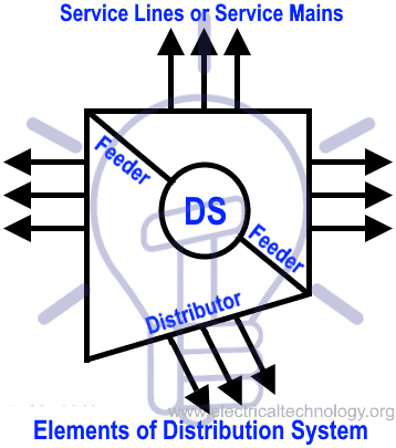
Feeders
Those electric power lines which connect generating station (power station) or sub station to distributors are called feeders. Remember that current in feeders (in each point) is constant while the level of voltage may be different. The current flowing in the feeders depends on the size of conductor. Fig 5.
Distributors
Those taping which extracted for electric power supply to the consumers or the lines, from where consumers get direct electric power supply is known as distributors as shown in fig 5. Current is different in each section of the distributors while voltage may be same. The selection of distributors depends on voltage drop and may be design according different level of voltage drops. It is because consumers should get the rated voltage according to the rules and design.
Related Post: Maintenance of Transformer – Power Transformers Maintenance, Diagnostic & Monitoring
Service Lines or Service Mains
The normal cable which is connected between Distributors and Consumer load terminal called Service Line or Service Mains. in other words, the cable which has been connected to the 11kV power lines (taken from step down transformer) to get three phase or single phase power supply. Phase or Live to Neutral power is 230V AC (120V or 240V etc in US) and 440V AC (208V, 240V, 277V or 480V etc in US) in three phase (phase to phase) system.
Related Articles:
- Effect of Harmonics on Power System
- HV And MV Switch Disconnectors And Isolators in Power System
- Primary and Secondary or Backup protection in a Power System
- Corona Effect & Discharge in Transmission Lines & Power System
- What is HVDC? – High Voltage Direct Current Power Transmission
- Types of HVDC Systems and MTDC Configurations
- Differences Between HVAC and HVDC – Power Transmission
- Advantages of HVDC over HVAC Power Transmission
- FACTS – Flexible AC Transmission System – Types of FACTS Controllers & Devices


this page is awsum. and wasim khan u r genius
Thanx for Appreciation. :)
good mashallah
Welcome Dear
wasim khan can u please clarify that in the primary transmission where there are three phase and 3 wires, why there are 6 lines instead of 3? thanks
nicely for imagination…..
Great write up as always..I wd like to get something straight: on distribution feeders, u said the current flowing depends on the size of the conductors..I think u meant to say the current flowing DETERMINES the conductor size. All in all great work. Keep it up. We all have room for improvement ☺
Absolutely right…Also Thanks for appreciation
My brother suggested I might like this web site. He used to be entirely right. This post truly made my day. You can not believe just how much time I had spent for this info! Thank you
three phase has only three wires or not?<br />
three phase has only 3 wires or more..?
star conn. needs 4 wire.<br />dlta conn. needs 3 wire.
In T&D (Transmission and Distribution) system, why use 11KV,22KV, 33Kv for 11 series only.plz explain friends
pls write me some notes and FAQs on electrical power generation , transmission and distribution
Sometime we come across 3 phase 415 V 50 hz electrical power supply. As noted in the above note said about of 400 V line phase supply. Is there any different between these two types of voltage?? What is the significant?
what is the best way for connection generation 600- 1000 MW if these generators near load center is it possible to connect them at 132 kv or to 400 kv
good lession conducted and i can study very well minus teachers and pess
wow…so informative..
Thanks 4 sharing
waaawoooooo fantantic.good notes