Traffic Light Control Electronic Project using IC 4017 & 555 Timer
Traffic Light Control Circuit – Simple Electronic Project
Introduction
Traffic Lights are used to control vehicular traffic on the road and publics streets. In the modern era, where everyone owns different types of vehicles resulting in a rise in the numbers of vehicles which leads to traffic jams and rush on the busy routes. That’s why traffic lights are mandatory for smooth traffic to avoid the traffic jams and accidents.
Basically, there are three lights in the traffic signal, each having a different message for the drivers. Red light (upper one) asks the driver to yield at the intersection, green light (last one) gives the driver free license to drive through the intersection whereas the yellow light (middle one) alerts the driver to wait if the next light is red one or get ready to go / turn the engine ON if the green light is next.
Traffic lights have proved to be an amazing way to stop vehicular collisions and control the traffic jams and divert the traffic in smooth lanes. Let’s see how to make a simple traffic light contol system using basic electonic components as follows.
Project Proposal:
As the name of the project “Traffic Light Control Circuit” suggests, the fundamental idea of this simple electronic project is to control the traffic via lighting signals. It can be used to avoid vehicular collisions and traffic jams as the system ensures the smooth flow of traffic even on the busy routes. This project is just a one-way traffic controller, although it can be further modified as well. In short, the circuit can be used to provides the instructions to the driver via lighting symbols whether to drive through, stop or yield at the intersection.
Control Lights indication:
There are three control lights or signals, which will provide the instruction to the driver.
- RED light – instructs the driver to STOP at the intersection.
- YELLOW light– instructs the driver to WAIT (If red light is next) or GET READY (if green light is next)
- GREEN light – instructs the driver to GO through the intersection.
Components Requirements:
Following is the list of the basic components, which we will be using to make our traffic light Control System.
- 9V Battery (Input battery)
- 100K, 22K and 330 ohm resistors
- 1µF, 10µF and 2.2mF capacitors
- Six 1N4148 diodes
- 555 timer IC (As a pulse generator)
- 4017 IC counter (Main IC of the circuit)
- 1M Potentiometer (Controls the timing of pulse generated by 555 timer)
- Red, Yellow and Green LEDs. (Output lighting signals)
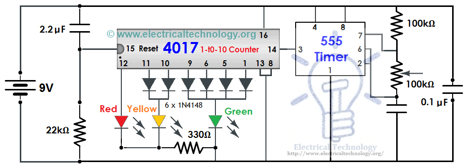
Circuit Diagram of Traffic Light Control mini Project
Click image to enlarge
Working Principle:
This traffic light circuit is designed based on a counter IC, which is mainly used in sequential circuits where a sequential circuit is used to count the numbers in the series. This way, we may call it a sequential traffic light system.
The working and operation of traffic lights control circuit, the main IC is 4017 counter IC which is used to glow the Red, Yellow and Green LED respectively. The 555 timer acts as a pulse generator providing an input to the 4017 counter IC.
The glowing time of certain LED lights totally depends upon the 555 timer’s pulse, which we can control via the potentiometer, so if you want to change the time of glow for a specific LED, you can do so by varying the potentiometer which is used to handle the setting of timing durations.
As the LEDs are not connected directly with the 4017 counter, hence the lights won’t be stable all the time. For this reason, we have used the combination of 1N4148 diodes and the LEDs in order to get the appropriate output lighting signals. The Main drawback of this circuit is that you are unable to set an exact timing using this configuration, however you will have the accurate estimated time period during the circuit operation.
Related Basic Projects with Circuit Diagrams:
- Automatic Street Light Control System using LDR & Transistor BC 547
- Automatic Bathroom Light Switch Circuit Diagram and Operation
- Automatic Doorbell with Object Detection By Arduino
- Automatic LED Emergency Light Circuit
- Automatic Night Lamp Using Arduino
- Automatic Plant Watering & Irrigation System – Circuit, Code & Project Report
- Fully Automatic Water Level Controller using SRF04
- Automatic Railway Gate Control System – Circuit & Source Code


thanks for the write up about trafic light control…please i need the conprehnesive note,the ways and proceduce to carry it out
verry good idea. bravo
Please send diagrsm for traffic light control rady diagram using 555 & 4017
Sir,
I want a detail information about transformer.
I need detail information about active & passive component
Electronics components that requires some voltage to activate them eg semi conductors ( diodes, transistors etc) are active components, while passive components are resistors, inductors, capacitors etc they don’t need voltage to activate them . some diode require 0.7v to activate them to rectify ac to DC.
Sir, the traffic light control system that I made by using ic 555 and 4017 in which glowing sequence and time interval isn’t so required. It is glowing very fast so, please tell me what should I do….??
There are little mismatch between components in image and description. I laid out this project on electronics workbench and does not work.
Can you give any offline software which help me to simulate electrical and electronics ckt and in which all components and all tools are available and which shows working condition of ckt and relay ,ldr and other coponents available
try using multisim or circuit wizard
Try ni multisim offline
help me
i need a four ways trafic lightx crt that functns well
Did you get that 4-way traffic control system.If so can you please send it to me! Actually I worked on one way control system I cleared it then as a part of next I tried in four way but I failed to do so! If you send it to me I will be more thankful!
Greetings Sir,
I am interested in making this project with my school students tomorrow, but I only have one question – Can I use actual bulbs in place of LED? And for that I will need to input AC Current so that the bulbs light up.
Can you please tell me, how can that be achieved. I will follow your design during making, kindly please instruct.
With Regards
You can use triacs. Best bet is to isolate your control circuit (555 & 4017) after the diode with an opto isolstor. The outputs of the isolator will go to the gate of the triac. First find total load of lamps then size triac current rating just over load current. The triac voltage should be rated to withstand peak to peak voltage. A 120VAC peak to peak is about 177 volts, so a trick rated above that should be fine. Finally you need to work out gate current and I believe that should work. Modern signal lights use LEDs, but there are still many incandescent signal heads out there. Keep in mind that AC current can be lethal, so be sure to do this as safely as possible.
Greetings Sir,
I am interested in making this project with my GOVT POLYTECHNIC COLLEGE KULGAM KASHMIR J&K CLASSMATES tomorrow, but I only have one question – Can I use actual bulbs in place of LED? And for that I will need to input AC Current so that the bulbs light up.
Can you please tell me, how can that be achieved. I will follow your design during making, kindly please instruct.
With Regards
If we want to glow three sets of leds at three different junctions what would be the circuit.
Sir, I was given a mini project on traffic light controller. So can u show me clearly how connections are to be made?
max cost ketli
If your project is not working do the following: buy 10 N4148 diodes instead of 6. Wire them as following:
1 tooth of the 4017 counter: connect using the diode to yellow led.
2 tooth of the 4017 counter: connect using the diode to green led.
(apply the instructions above to the list below)
3 tth: green led.
4 tth: green led.
5 th: red led.
6th: red.
7th: green.
8th: (as the drawing, connect to the ground wire).
9th: red.
10th: yellow.
11th: red.
This way, there are 4 states of green, 2 states of yellow and 4 states of red.
need your guidance with my project
is there any alternate to 4017 ic
also can u give me the pcb layout of this circuit
parkerleono@gmail.com
I am trying to simulate the program using mikroC controller but still i observe problems may you provide to me the codes please
please i need the conclusion,limitation,and recommendation of this project
Hi Ramatu, glad to know you are in the same game as me
where should we connect the potentiometer
Where we have to connect the potentiometer
i need the working of all the components..will you plzz……
Hello,
I wan to know if your establishment undertake traffic light control manually from an outstation.
i’ve made it but the lights are changing very fast even when i change the potentiometer can anyone help please
The circuit is NOT correct as drawn! Notice the potentiometer wiper arm is NOT connected to anything. If you connect this to either the upper or lower lead then you can change the time of the 555. Also the parts call for a 1 Meg Ohm Pot. That’s too large. Try a 100K as drawn. I’ve drawn up this circuit in Proteus and it works great.
Please submit to the following Email Address: eeetblog@gmail.com. We will review it and Will republish with your name and contribution. Thanks and best wishes.
And change the 100K resistor to a 10K one and you will get a one second pulse out of the 555.
Can you send a picture of the circuit that you have drawn on Proteus on this email address: muhammadrashidshafique@gmail.com
I will appreciate it and thank you!
Hi I want to make small adjustments on the traffic lights, like , if any car bypass the traffic light, an alarm will Horn, how will I synchronize the alarm to the traffic light?
very important ihave just got a patent for energy saving aperatus for traffic signal using less than 9 watt of electric with 12 to 24 volts terific power saving weight total less than 15 lbs can also be used by solar energy input 120 v output 12-24 volt . isent it great.
hello, I am a student using your schematic for my electronics class as a project proposal. I am wondering if you would be able to provide me with the pcd layout of this or possibly a photo of your working proto-type? I would greatly appreciate it and thank you.
kev.vin_basilio@yahoo.com
please, may somebody help me in carrying this practical. its what the gave to me as my project topic but i don’t how to start
i want to know detailed function of each component of the traffic light circuit.
plz send me on the email id vickybipulroy@gmail.com
Hi ,
I have a Traffic light probably serviceable – which I picked up from scrap.
The circuit board and components seem to be intact. The LEDs and the Black plastic dome cover all are in place
My question is : If i send a picture of the same would you help with your comments as to whether I can connect a 9V cell to see if it is still working.
What tools do i use for this project?
pls Sir. I was given a similar project topic for my final proposal. pls sir I will be so glad if I can get the urgent details of the project and may God bless u sir.
Daniel.Akinpelu@gmail.com
I need a four way traffic light which uses 12volts