Clap Switch Circuit Using IC 555 Timer & Without Timer
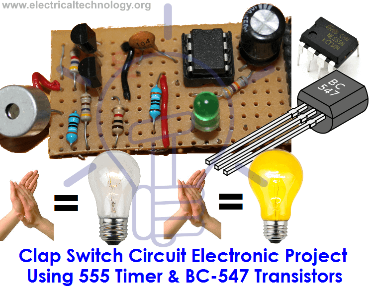
Clap Switch Circuit Electronic Project Using 555 Timer & BC-547 Transistors
Introduction to Clap Switch Circuit
Clap Switch is a basic electronics mini-project, made with the help of the basic components. Clap Switch has the ability to turn ON/OFF any electrical component or circuit by the clap sound. We will use two basic clap switch circuit diagrams i.e. (With IC 555 Timers and without 555 Timer).
It is known as Clap Switch because the condenser mic which will be used in this project will have an ability to take the sound having the same pitch as the clap sound as the input. Although it doesn’t mean that the sound will have to be exact the clap sound, it can be any sound having the same high pitch as clapping sound. We can also say that it converts the sound energy into the electrical energy because we are giving an input to the circuit as a sound whereas the circuit gives us the output as an LED light when glows (electrical energy). In more simple words, the circuit is able to convert the sound energy to activate the circuit and led provide electrical energy as an output in the form of heat and light.
Related Electronic Projects:
- Automatic Plant Watering & Irrigation System – Circuit, Code & Project Report
- Smart Irrigation System – Circuit Diagram and Code
Also Check:
- Traffic Light Control Simple Electronics Project using IC 4017 & 555 Timer
- IC 555 Timer Online Calculator with Formulas and Equations
Required Components
As already mentioned, this project is basic electronics mini-project, so this project is made of the basic electronic components.
Following is the list of the components required to make the Clap Switch.
- 1k, 4.7k, 47k, 330 and 470 ohms resistors
- 10µF and 2 100nF capacitors
- Electric condenser Mic
- Two BC547 transistors
- LED
- 555 Timer
- 9V battery
Working Principle of Clap Switch Circuit
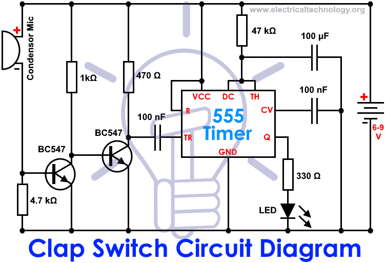
This circuit (As shown below) is made with the help of Sound activated sensor, which senses the sound of Clap as input and processes it to the circuit in order to give the Output. When sound is given as the input to the Electric Condenser Mic, it is changed into the Electrical Energy as the LED turns on. LED turns ON, as we give sound input and it turns OFF automatically after a few seconds. Turn-On LED timer can be changed by varying the value of 100mF capacitor as it is connected with 555 timer whose main purpose is to generate the pulse.
Although the name of the circuit is the Clap Switch, you are not restricted to give input as the Clap only. It can be any sound, having the same pitch as of Clap so this can also be called as “Sound Operated Switch”. This circuit is mainly based on transistors because the negative terminal of Mic is directly connected with the transistor. In this circuit, we haven’t used any Electronic Switch to turn on/off the circuit, so when you are connecting the battery with the circuit, it means your circuit is now turned ON and it will take the inputs in the form of Sound Energy. You can modify this circuit by using Relay as Electronic Switch to turn the circuit ON or OFF.
As soon as we give the sound input to the circuit, it amplifies the sound signals and proceeds them to the 555 timer which generates the pulse to the LED, making it turn ON. You are to make sure, that the negative side of the Condenser mic is connected with the amplifier or the circuit will heat-up and may not work with different models of transistors etc. You cannot increase the sensitivity of the Condenser mic for long usage, it has a short range by default. It is also applicable to the LAMP and fans and other electrical appliances, so this circuit has many opportunities for modification.
- Related Project: Voice Recognition Based Home Automation System
Clap Switch Schematic Circuit without 555 Timer
To make the same circuit as mentioned above without IC 555 Timer, We will have to use the following basic electronic components and devices.
| S. No | Component Name | Code | Value | S. No | Component Name | Code | Value |
| 1 | Resistor | R1, R9, R12 | 2.2kΩ | 10 | Capacitor | C2 | 1µF /50V |
| 2 | = | R2 = | 470kΩ | 11 | = | C4 | 47µF /16V |
| 3 | = | R3 = | 47Ω | 12 | Diode | D1, D2 | IN4148 |
| 4 | = | R4, R6 = | 4.7kΩ | 13 | LED | D3 | Red |
| 5 | = | R5, R8, R10, R11, R13 | 10kΩ | 14 | Transistors | Q1, Q2, Q3, Q4 | 9013 |
| 6 | = | R7 | 470Ω | 15 | Microphone | MK1 | 9767 |
| 7 | = | R14 | 1K | 16 | Cable Terminal | J1 | 2.45 2P (Horizontal) |
| 8 | Capacitor | C1, C5, C6 (Ceramic) | 104 (0.1μF) | 17 | Power Wire | 1 | 2.45 2P (Single) |
| 9 | = | C3 (Ceramic) | 103 (0.01μF) | 18 | PCB | 1 | FR-4 28*49 |
Related Post: Automatic Street Light Control System.(Sensor using LDR & Transistor BC 547.)
How Clap Switch Circuit Works without 555 Timer?
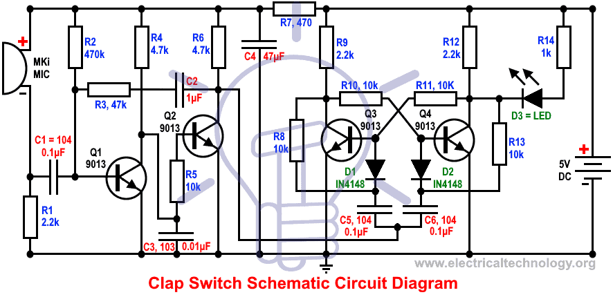
This circuit operates based on bi-stable trigger and audio frequency signal.
Audio signal accepted by MK1 goes to the base of transistor Q1 through capacitor C1. When amplified, it goes to the base of transistor Q2 through collector of transistor Q1. The bi-stable circuit trigger when they get a negative square wave from collector of transistor Q2.
Resistor R1 and capacitor C1 restrict the circuit frequency to high sensitivity range of 3kHz. When the power supply is ON, transistor Q3 saturated and Q4 is cutoff, so the diode D3 is OFF. When the MK1 microphone gets a control signal (clap or any other similar sound), The amplified negative square wave and negative pulse enters to the base of transistor Q3 through diode D1 after differentiation process. So the power turn ON and D3 LED diode glows.
The power turn OFF again when a control signal enters to MK1 microphone which leads the LED diode D3 switch off. To use other external control devices and equipment, J1 (Cable terminal can be used for this purpose). J1 and relay can be connected to control other appliances by clap or sound control system. Keep in mind that a reverse diode should be connected at the end of the relay to perform this operation.
Note: The operated voltage for clap switch circuit without timer is 5V DC while 6mA current is needed to glow the LED light (When current is less than 3mA, LED won’t glow).
Related Electron Projects:
- Automatic Bathroom Light Switch Circuit Diagram and Operation
- Automatic Doorbell with Object Detection By Arduino
Click schematic diagram to enlarge
Advantages & Disadvantages of Clap Switch Circuit
- It can be used to turn ON and OFF the LED or LAMP simply, by clapping your hands.
- We can also remove LEDs and place a FAN or any other electric component on the output in order to get the desired result.
- The Condenser Mic used in this circuit has the short range as a default, which cannot be varied.
Applications of Clap Switch Circuit
Clap Switch is not restricted to turn the LEDs ON and OFF, but it can be used in any electric appliances such as Tube Light, Fan, Radio or any other basic circuit which you want to turn ON by a Sound.
You may also check these simple and easy DIY EE Projects: Electrical and Electronics Projects
Related Basic Electronic Projects:
- Electronic Circuit Breaker – Schematic and Working
- Fully Automatic Water Level Controller using SRF04
- USB Propeller LED Fan Clock – Circuit Diagram & Project Code
- 24V Flasher Circuit
- Early Flood Detection System Using Arduino – Source Code
- 12V to 5V Converter Circuit – Boost and Buck Converters
- Dual Power Supply Circuit Diagram – 230VAC to ±12VDC
- Basic Voltage Doubler Circuit Diagram using 555 Timer IC
- How to Make a Voltage Tripler Circuit?
- Simple Cell Phone Charger Circuit Diagram – 5V from 230V AC
- Automatic Railway Gate Control System – Circuit & Source Code
- Electronic Relay Switch Circuit – NPN, PNP, N & P Channel Relay Switches
- LED Roulette Circuit Diagram using 555 Timer & 4017 Counter
- Distance Measurement Using Arduino and Ultrasonic Sensor
- Variable Power Supply Using Arduino UNO – Circuit and Code
- Simple Overvoltage Protection Circuit using Zener Diode
- Top Electrical Projects ideas for Engineering Students


MUY INTERESANTE Y SE PUEDE APRENDER Y DESARROLLAR TODA CLASE DE CIRCUITOS TANTO ELÉCTRICOS COMO ELECTRÓNICOS,
Very useful sharing
certainly very useful and easy to attempt ckt.
hi sir i am intersted in daigram of electronics
how can we run other devices such as radios etc in such a simple device?
BY CONNECTING A RELAY
what a relay
please send me clamp circut and digrame
on my email if readymade is avilable please send me how many your rait of your circuit
“Turn-On LED timer can be changed by varying the value of 100mF capacitor as it is connected with 555 timer” does this mean I can change the time by lowering the value of capacitor? high? please answer . thanks
bulb is not permanently on/off why
hi good day . I need help for this circuit . what is the purpose of the capacitor connected bet. collector pin and trigger .
witch transistors can i use instead of BC547? PLEASE REPLAY
BC 548 OR 2N3904
How can i defend my project base on this topic
For a 2nd/3rd year undergrad project this is very good. If someone can fully explain the beauty of this whole circuit I will give them 10/10.
1. Microphone is a passive device. Its resistance changes with sound. R1 converts into a voltage divider so that its change in resistance will convert into change of voltage at the junction that C1 pick up.
2. C1 does 2 things. 1. It blocks DC current from R2 from interfering with microphone. 2. It attenuates signals lower than 3 KHz. So that only a sudden loud sound can trigger the switch.
3. Signals from C1 modify the voltage level at the base of the transistor. But the transistor base is forward biased, it stays at .6 V, the voltage across R2 changes. It changes the current through R2, which will change the base current of Q1.
4. Q1, R2 and R3 give 100x amplification (470k/4.7k)
5. Base of Q1 also gets feedback from output of Q2, which is the most clever part of this circuit. It amplifies the signal so much that it will turn the output into a square wave
6. C3 is important to ensure that there are no unwanted oscillations at the output.
7. R6, Q2 and R5 give further 2x gain. C2 blocks DC current from collector of Q2 from going back to base of Q1.
8. Rest of the circuit is a T-flipflop. Collector of Q3 goes to base of Q4 and collector of Q4 goes back to Q3. This positive loopback makes it remember its state.
9. C5 and C6 are high pass filters that convert the output of Q2 into a clock pulse for the flip-flop.
10. D1 and D2 are essential to ensure that clock pulse flows only in one direction.
11. Pulse from the diodes momentarily overrides the base voltage of Q3 and Q4. If the base is already low, then there is no change. If it is high, then it gets pulled low. It causes its collector to go high and that in turn turns on the other transistor and hence the state of the flip-flop changes.
12. Feedback from R8 and R13 is what converts an RS flip-flop into a T-flip-flop.
13. C4 and R7 form low pass filter that filters out flip-flop toggles from disturbing the microphone.
14. Beyond that you can connect a suitable driver and drive any load from the output of Q4. It can be a light, relay, motor or anything.
Hi,
I have been trying to build the clap switch circuit using the 555 timer chip but I don’t have any BC547 transistors. I have tried using 2N3904, C1815 and BC108 all with no success. I can’t figure out what is the problem. Can anyone help? I would be most grateful.
Kind regards,
James
2N3904 can used instead of BC547.BUT THE CLAP LIGHT USING 555 IC DIDNT WORKED PROPERLY.IT ONLY WORKED FOR 5-6 SEC
Where are u from bro.
Can we connect the switch directly to AC current
No.you should connect transformer or adaptor or other similar
Permanently on/off, how can I modify?
Its seems good, but I want to remove LED with an energy saving lamp of 24 watt, can I do this. Also tell me what is the voltage at output pin of NE555. And what will be the max output current.
Thumbs up for you… (y)
Output is accordance to LED voltage… By the way, You can connect Relay instead of 555 Timer
Hey sir/mam,I requested you to describe me more and more applications of clap switch as a project.
how can i make the ON permanently after a single clap and OFF
Yes Sure…
My ckt didn’t work perfectly …… L.E.D is On on clap but not Off by clap… How can i fix this plz help
sir/mam .. if i will put a 5 pin relay switch in the circuit where should i put it and what will be the effect of it ? please anwser me anybody …
.. elow … i need help .. if i will put a 5 pin relay switch in the circuit .. where i should put it and what will be the effect of it …. plss i need some advice …
can i replace the LEd with a low V amplifier ??
its interesting….to design …my first project
Many Many Thank`s
Thank You With Regards.
Tamal
I need this cirite but i tried it for 5 times on my bread board and bought its commbounts for 5 times!!
And its not working olease help me please
bro i tried many times but everytime led is on and clap is not working :(
Same Here. Need Help.
I implemented this circuit on a breadboard. When I clap near the microphone, the L.E.D turns on for nearly 6 seconds and then, turns off automatically. I want to make it work like a real clap switch. For example: the L.E.D turns on the clap and turns off on a clap. Please can help me in figuring this one out.
What an interesting project where i can connect and work out.
NB,. Am doing a project on a clap switch please send for me more of the literature review about this field.
thanks
hlw sir plz explain the ic points??i means 1,2,3,4,5,6…it will b easy for jointing the other compunents with IC..
please admin can you for another circuit diagrame that support both on and off signals
how work the clapp switch
Hi, I’ve done everything as per the design but its not working. I’ve doubt on mic. Is there any way to check whether mic is working or not?
dude…..for those capasitors…..what volt it is?
our circuit is direct on.pls give me sollution
hi mam/sir, my project has already worked, but when I accidentally short it with its aluminum casing, it didn’t worked now, the led just on when you put the 9v supply, I replace the mic and it’s two transistors but also it didn’t work out…. Pls help me!!!…. tnx
Thanks Engineer for the project, am more interested in the project and i would like to request you to send me the literature review of the project in my email.
Should I use electret condenser mic???????????
How much volt of 10uf capacitor plz reply fast
can i use 100 nf instead of 100 uf.,…………?
how much of frequency and amplitude genrated while clapping our hands
Sir please please please help me.
Why my circuit isnt working.?? When i finish set up my circuit then i put the battery. The baattery light up without clapping. Its like i connect the battery directly to the LED… its hav been 2 months im working for this Final Year Project. Pleaseees. Im stress out
+60133145296
suzumiya96@gmail.com
it is working great thank you!!!!!!!
kindly send the pcb layout of this we will be thankful.
hey mens i need support i want use to us this circuit to control AC lamp what can i do
HOW CAN I use this circuit to cantor ac lamps
Hy mens in the working principle is that 100mF or 100Nf
hy my circuit isent running help me
sir the value off capacitor(10nf) in the list is not same as in circuit diagram
Check it again, We have it in the circuit diagram…
Led is always on…no Change…what to do
Nob no de na bhai please kam h mera same project h
reI want to believe that other electrical appliances you can apply this to has to be DC appliances since the voltage source is 9volts else you will to apply AC signal and do rectification
which microphone did you use for the circuit?
Is there any video available of this project.. it will help us.
4.4V TO 5V ITS WORKING PROPERLY FOR TRANSISTOR CIRCUIT AND BUT BELOW THAT ITS NOT WORKING.plEASE HLEP ME WITH THAT
Wow !! that positive feedback in the transistor circuit is such a genius idea. I was struggling without it. Generally positive feedback is considered bad, but it has been used so cleverly in this circuit. It really pushes the second stage to saturation and cut-off without which it cannot trigger the next stage. The capacitors added to the trigger circuit are also just right to allow audio frequencies. That 103 capacitor at the output of first stage is also genius, without that the switch won’t remain stable. Very clever well thought out design. Worked like charm !!