Steady State Error & PI Controllers
Steady State Error & PI Controllers – Effect of PI Controller on Steady State Error
A steady-state error is defined as the difference between the desired value and the actual value of a system output when the response has reached the steady state. Steady state error is a property of the input/output response for a linear system. In a good control system, steady-state error should be minimum.
Let’s consider a transfer function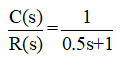
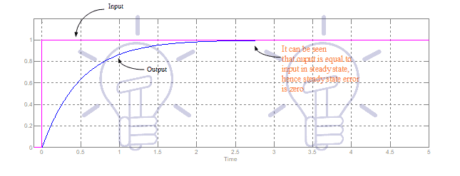
It is a simple first-order transfer function, having gain is equal to one and time constant 0.5 seconds. Against unit step input, its response is shown in Figure-1. It can be seen that in steady state, output is exactly equal to input, hence the steady-state error is zero.
Against unit ramp input, its response is shown in Figure-2. It can be seen that in steady-state there is a difference between input and output hence there is a steady-state error.
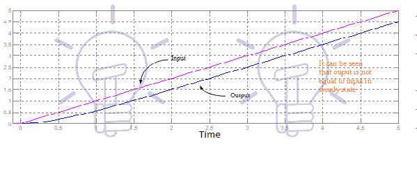
(In control system books you can find that against ramp input, steady-state error in first-order transfer function, is equal to the time constant. It can be seen in Figure-2 that steady-state error is equal to 0.5. For example at 3 seconds input is 3 while the output is 2.5, hence the steady-state error is 0.5)
Please note the following important tips;
- Steady-state error is highest if the input is parabolic, may be lower if the input is ramp, further lower if input is step input. As in aforesaid explanation, you can see the steady-state error is 0.5 against ramp input, and it is zero against step input.
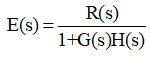
- The steady-state error depends on input. In a feedback control system error signal can be found as
 Steady state error can be found as
- Stability does not depend on the input. It depends on the denominator of transfer function.
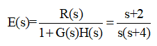
- Let’s a transfer function as
 The steady-state error depends on R(s), while stability depends on 1+G(s)H(s). ‘1+G(s)H(s)=0’ is called characteristics equation. Its roots indicate the stability of the system.

Now, we will explain, steady-state error in a closed loop control system with few numerical examples:
Example 1:
Consider the following control system (system-1) as shown in Figure-3:
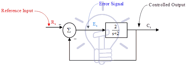
Let, reference input ‘Rs’ is unit step input, then in the transient period, Error signal ‘Es’ and output ‘Cs’ both will continuously change but in steady state period (when the system is settled), ‘Es’ & ‘Cs’ will have fix values. (It is not necessary in all cases. For example, if ramp input is applied in this system, then conditions may be different).
Various steady state values of system-1 is shown in Figure-4.

It can be viewed that the steady-state value of the error signal is 0.5, hence steady-state error is 0.5. If the system is stable then various steady-state values can be obtained as follows:
In transfer function keep s→0, you will get steady-state gain of transfer function.
You can calculate the value of output as follows:

Steady state value of any signal can be calculated with the above method. For examples
Input is R(s)= 1/s (Input is unit step input)
Its Steady state value is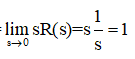
Similarly, the error signal can be calculated as:
Steady state value of error signal (steady-state error) is
Also, it can be seen from Figure-4, that difference in input & output is 0.5, hence the Steady-state error is 0.5.
Another method to calculate steady-state error is as follows:
Calculate Positional error coefficient ![]() You will find Kp=1,
You will find Kp=1,  You will find the same answer.
If the input is a step input, say R(s)=3/s (it is step input, but not a unit step input), than steady-state error will be 
If the input is unit ramp input, then
Calculate, Velocity error coefficient Kv is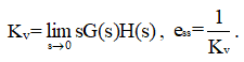
If the input is unit parabolic input, than
Calculate, Acceleration error coefficient Ka is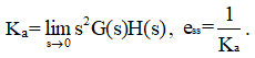
Effect of PI Controller on Steady State Error:
PI controller (Proportional plus integral controller) reduces the steady state error (ess), but have negative effect on the stability. PI controller reduces the steady state error, it is an advantage; but PI controller reduces the stability also, it is the disadvantage. PI controller reduces the stability, it means, damping will decrease; peak overshoot and settling time will increase; Roots of characteristics equation (poles of closed loop transfer function) in left hand side will come closer to the imaginary axis.
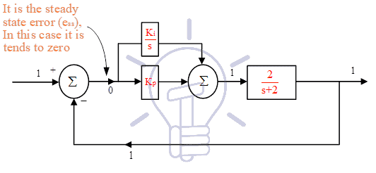
Now, we will add one PI controller (Proportional Plus Integral controller) in system-1 and examine the results. After adding PI controller in system-1, various steady state value are shown in Figure-5, It can be seen that output is exactly equal to reference input. It is the advantage of PI controller, as it tries to minimize steady state error, so that output will follow the reference input.
Transfer function of PI controller can be calculated as
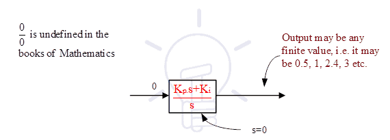
One question can be asked that if input of any transfer function is zero than its output should be zero. So, in present case input to the PI controller is zero, but output of PI controller is a finite value (i.e. 1). This explanation is not given in any control system book*, hence we will explain it:
- Steady state error is not exactly zero, its tends to zero, similarly s≠0, it is s→0 , So let at any instance steady state error is 2x10⁻³, at the same time ‘s’ is also equal to 2x10⁻³, hence output of PI controller is ‘1’.
(1) Lets consider another control system shown in Figure-6:
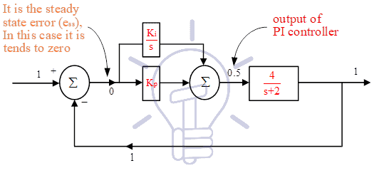
In this case we can say, at any instance suppose, steady state error is 2x10⁻³, at the same time ‘s’ is equal to 4x10⁻³; (Note that denominator of PI controller is ‘s’, mainly we are talking about this one) hence output of PI controller is ‘0.5’. It means ess and ‘s’ both are tends to zero, but their ratio is a finite value.
In the books of control system you will never find s=0 or t=∞, (because time cannot be infinity), you will always find s→0 or t→∞
(2) Second explanation is that Steady state error is zero, s is also zero in steady state. PI controller transfer function is  In the books of mathematics you will find that 0/0 is undefined, so it can be any finite value (refer Figure-7).
(3) Third explanation is, 1/s is an integrator. Input is zero, integration of zero is undefined. So output of PI controller may be any finite value.
One Basic Difference in Open Loop Control System & Closed Loop Control System
In reference to above explanation, we will explain one basic difference in open loop control system & closed loop control system. Differences in open loop control system & closed loop control system, you can find in any book of control system*, but one basic difference which is related to above explanation is given here:
An open loop control system can be represented as follows:

Any closed loop control system (feedback control system) can be represented as follows:

Transfer function of plant is fixed. In all our discussion, we have assumed H(s)=1; An operator can control the transfer function of controller (i.e parameter of controller such that Kp, Kd, Ki) etc. Controller can be proportional controller (P controller), PI controller, PD controller, PID controller, Fuzzy logic controller etc. There are two aims of a controller (i) To maintain stability, i.e. damping should be 0.7-0.9, peak overshoot and settling time should be low. (ii) Steady state error should be minimum (it should be zero). But if we will try to increase the damping than steady-state error may increase. Therefore designing of controller should be such that both (stability & steady-state error) should be well maintained. Optimum designing of controller is a vast research topic.
As written earlier, PI controller reduces the Steady state error (ess) drastically, but have negative effect on the stability.
Now, we will explain one basic difference in open loop control system & closed loop control system, which is related to above explanation.
Consider Figure-10; it is an open loop control system.
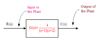
Let input is a unit step input. So, Steady state value of input is ‘1’. It can be calculated that steady state value of output is ‘2’. Suppose there is a change in transfer function [G(s)] of plant due to any reason, what will be effect on input & output? Answer is input to the plant will not change, output of the plant will change.
Now consider Figures-11 &12


It is a closed loop control system (Figure-11). Suppose there is a change in transfer function of plant due to any reason, what will be effect on input & output? In this case, input to the plant will change, output of the plant will remain unchanged. Output of the plant will follow reference input. Figure -12 shows the new conditions, in which plant parameters is changed. You can see plant input is changed to 0.476 from 0.5, while the output is not changed.
So, you can understand, in open loop control system output of plant is changed while in closed loop control system input to the plant is automatically changed, while output tries to remain constant.
In the books of control system, you can find the following sentence:
“ In case of parameter variation of plant transfer function, Closed loop control system is less sensitive as compared to open loop control system” (i.e. variation in output of Closed loop control system is less as compared to open loop control system).
We hope above statement will be more clear with the examples given in this articles.
________________________________________________________________________________________
* Dear Readers, purpose of these articles is not to reproduce the topics already available in the books; but our aim is to present various complex topics of Control Engineering in easy language with numerical examples. We hope this article will be helpful to you to understand various complexities about steady state error & PI controllers.
Related Posts: