How to Connect Automatic UPS / Inverter to the Home Supply System?
Automatic Inverter / UPS System Connection & Wiring Circuit Diagram
Introduction to Automatic Inverter / UPS Wiring
Power failures and emergency breakdowns may occur at any time due to short circuits, damage to transmission lines, substations, or other parts of the distribution system, as well as storms and severe weather conditions.
In such cases, an emergency generator or battery backup system can be used to restore power to homes and connected appliances. In some situations, it is critical to restore power immediately, for example, in hospital ICUs, military installations, intelligence and security systems, and offices. This is where generators and Inverter/UPS (Uninterruptible Power Supply) systems, supported by backup batteries, play an important role.
For this purpose, we demonstrate the wiring and connection of an automatic UPS/Inverter system for home or office supply. We also provide different tutorials on UPS/Inverter wiring & installations in home distribution boards, including manual setups, automatic systems, and those with auto or manual changeover switches.
- Related Posts: Automatic UPS / Inverter Wiring Diagram using One Live Wire
Why & Where We Need Auto UPS / Inverter System?
As mentioned above, power failures and blackouts can happen unexpectedly for many reasons.
In some cases, you need a continuous and uninterruptible power supply for sensitive systems such as security networks, hospital operating theaters and ICUs, airports, military bases, intelligence systems, and other critical electrical networks.
In more common scenarios, such as routine load-shedding, lack of a secondary power source (generator, solar, wind, etc.), low voltage issues, or insufficient stored battery power, you may still require uninterrupted supply for your home, office, PC, or certain rooms and load points. In all these situations, an automatic UPS/Inverter wiring connection to the home panel board is essential.
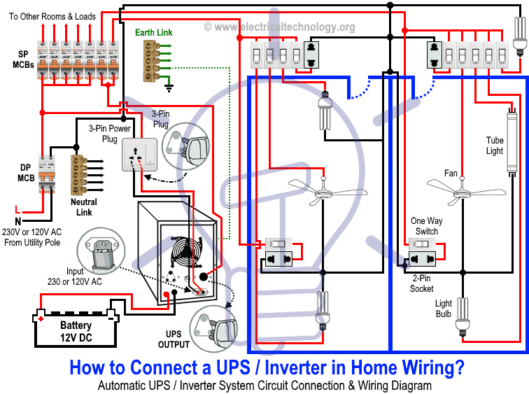
How to Connect a UPS / Inverter to the Home Supply System?
To connect an Inverter/UPS to the home electrical supply system, follow these steps:
- Disconnect the Live (Line) wires of the circuit breakers (for the selected rooms) from the main distribution board, which are connected through the main double-pole switch. These are the circuits you want to connect to the automatic UPS supply.
- Suppose you want to connect two rooms to the UPS system. Disconnect their Live wires from the main supply and reconnect them through the UPS output, via two single-pole MCBs (separate from the main panel).
- Only these two connected MCBs, and their corresponding loads will receive continuous power during a blackout.
- To recharge the battery, connect the UPS input to the outgoing terminals of the main double-pole MCB through a 3-pin power plug and socket.
The diagram below illustrates this connection: only the selected two rooms are powered by both UPS and batteries (as well as the main supply), ensuring uninterrupted power for lighting and fans. Other loads remain powered only by the main supply.
Click image or open in a new tab to enlarge
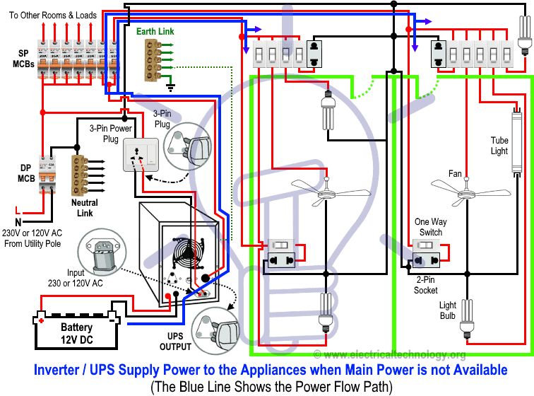
Working Principle & Operation of Automatic UPS / Inverter
1. When Utility Power is Not Available
During a blackout, power flows from the batteries through the UPS, which converts 12V DC into single-phase AC (230V in UK/EU or 120V/240V in US/Canada). The connected rooms and appliances continue to operate without interruption.
In the diagram, the BLUE LINE indicates power flow from the battery through the UPS to the load points.
Click image or open in a new tab to enlarge
Related Post: How to Connect a Portable Generator to the Home Supply – 4 Methods
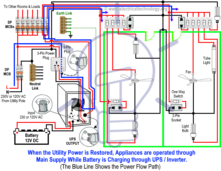
2. When Utility Power is Restored
When the main supply returns, all home appliances operate normally on utility power. At the same time, the UPS charges the batteries by converting AC supply (230V/120V) into 12V DC for storage.
In the diagram, the BLUE LINE shows power flow from the main distribution board through the UPS to the load points.
Click image or open in a new tab to enlarge
Wiring Color Code:
Wiring Color Codes
We have used the following colors in the wiring diagrams. You may use according to your local area code i.e. NEC, CEC, IEC, AS/NZS etc.
- Single-phase (General – used in many countries):
- Red = Live (Phase)
- Black = Neutral
- Green = Earth (Ground)
- NEC (US & Canada, 120V AC single-phase):
- Black = Live (Line)
- White = Neutral
- Green/Yellow or bare = Ground (EGC)
- IEC (UK & EU, 230V AC single-phase):
- Brown = Live (Line)
- Blue = Neutral
- Green/Yellow = Earth
Related Posts:
- How to Wire Solar Panels in Series, Parallel and Series-Parallel?
- How to Wire Batteries in Series, Parallel and Series-Parallel?
General Precautions When Playing with Electricity
Resources and Related Electrical Wiring Installation Tutorials.
- How to Wire Wire a Single-Phase Distribution Board [Consumer Unit]?
- How to Wire a Distribution Board with RCD – Single Phase ?
- How to Wire 120V & 240V Main Panel? Breaker Box Installation
- Single Phase & Three Phase Wiring Diagrams (1-Phase & 3-Phase Wiring)
- Home Electrical Wiring Installation Diagrams & Tutorials
- Single Phase Electrical Wiring Installation in Home – NEC & IEC
- Single Phase Electrical Wiring installation in a Multi-Story Building
- Three Phase Electrical Wiring Installation in Home – NEC & IEC
- Three Phase Electrical Wiring Installation in a Multi-Story Building
- How To Wire a Single Phase Energy meter?
- How To Wire a 3 Phase kWh meter?
- How to Control One Lamp From Three Different Places?
- Staircase Wiring Diagram – How to Control a Lamp from Two Places?
- Difference Between Inverter & UPS (Uninterruptible Power Supply)
- Difference Between Voltage Stabilizer and Voltage Regulator (AVR)
- How to Determine the Suitable Size of Inverter for Home Appliances?
- How to Wire Solar Panel to 120-230V AC Load and Inverter?


not so impressive
Hmm..May be…But you can also check another one in the next post
I was doing this in the early 90’s using computer UPS, it ran several lights, small television, and a fan. I used Jumper cables to supply 12VDC from my Vehicle, and left the car running til the power came back on
Wow… A legendary idea….
Is neutral connected to the main neutral? as per diagram
Yes
Yes bro
Nice work.
Thanx Dear
thank you so much dear
Most Welcom
Hi,<br /><br />UPS input and output neutral is shot circuited? Is this ok<br />If UPS for one room and generator for other room is connected … Still can we connect UPS outout neutral wire to mains ?<br /><br />thanks
♦ its not short circuited…, when Phase touch neutral without load then Short circuit occurs. <br />♦ refer to the other diagrams for this purpose under the " Electrical Wiring",→UPS Wiring diagrams.
sir how many watts ups and battery good for 5 fans and 5 lamps <br />
1200w
175AH
House waring
Amjad Islam @.. what is the rating of Fans and lamps ( in Watts)?
Electric
Yes
For 5 fans and 5 lamps( energy saver) 1000 watts UPS with 2 batteries of 180 Amp/Hr is good, its have better efeicency. ok
how to change the frequency of a ups? i heard that there is a knob in it for the purpose<br />
May be…
Thanks i do very easily.
Welcome
This is my very first time I have visited this website. I found lots of interesting stuff in your blog.<br /><a href="http://www.adeptpower.co.uk" rel="nofollow">Generator Maintenance</a>
Seems to me like there isn't enough protection from the main switch to the UPS in case of a short circuit in this area.
thanks sir i found lot of info from this for my project work for my school level
Welcome dear
I disagree with the first comment. I think it is valuable and informative post..
Thanks for appreciation…
You described many interesting elements in your post. Thank you very much for such informative blog.<br />https://plus.google.com/104896718356367167029/about
I dont think it's save
I want to connect only one points example. Only c.f.l but where more points.how to do? Conection
sir i need to contact u for a similar kind of project, plz tell how to contact u , regards <br />haider
Hello Wasim Khan..first of all a very big thanks to you…<br /><br />Your description with the diagram is just very very simple to understand…<br /><br />But I have a few queries which I want to ask you. If you describe and simplify my these queries then I am going to install an inverter in my home as installing an inverter is very urgent in my room.<br /><br />My queries are simple. They are:
Did you check other UPS connection diagrams in the Electrical "Wiring Section" ? Reply.
Hello Wasim Sir,<br /><br />Thanks for your Concern and reply.<br /><br />Yes I checked that post too in here https://www.electricaltechnology.org/2012/11/automatic-ups-system-wiring-circuit_23.html…<br /><br />Thats why I was little bit confused. As you suggested on that post to connect an extra phase wire with all those equipments to inverter output phase point only and no need to connect
Please give me the right solution sir..<br /><br />I am waiting to hear from you. Please give me the right solution so that I can install an Inverter for my room. Its urgent.<br /><br />Thanks.
Dear… in your case, you may use the following diagram..i.e you may connect another wire as Live wire…<br />here is the diagram<br />https://www.electricaltechnology.org/2012/11/automatic-ups-system-wiring-diagram-in.html..<br /><br />also, if you cant manage that diagram (As mentioned in the above link) then you should follow the same diagram as shown in the above post.<br />in this diagram,
<br />eDon't worry…I am using the same wiring diagram, that why i suggested to you… <br />The working of these diagrams ar:<br />When main supply available… your all appliances will work on Main Supply..as will as, it will charge your battery..<br />When main supply not available… Only those appliances will work which you have been connected to Inverter (UPS)…<br />Thanks
I have read all your automatic ups wiring post.<br /><br />I am clearing my doubts again…this time not in complicated way.. :)<br /><br />I want to connect some of my electrical equipments of my house with Inverter. When main power house supply is available then all electrical equipments as well as those inverter connected equipments should also work over main power supply (not from battery).
Dear… in your case, you may use the following diagram..i.e you may connect another wire as Live wire…<br />here is the diagram<br />https://www.electricaltechnology.org/2012/11/automatic-ups-system-wiring-diagram-in.html..<br /><br />also, if you cant manage that diagram (As mentioned in the above link) then you should follow the same diagram as shown in the above post.<br />in this diagram,
Thank you very much Sir… :)<br /><br />I'll do what you have told me to do. I think I have figured it out on which way should I follow as per your diagrams. Your posts helped me a lot.<br /><br />And I want to say thanks again and I will reply you again as soon as I successfully complete the wiring and installation of the inverter.<br /><br />Take care.
Most Welcome Dear… and Take Care,,, Best wishes,,:)
Dear Sir, do we have to connect Neutral from the output plug of the UPS? Because you said in your previous diagrams that there is no need to connect a neutral wire since it is assumed to be already connected to the mains electricity? Thanks. It's a bit of a contradiction from the previous diagram!
Yes… You have to connect the Neutral Wire from UPS (Output) to the main neutral link.<br />
My question, is really on why is important to connect the neutral wire from UPS (Output) to main neutral link? Wouldn't it short-circuit?<br />
No
Plus one more question from the phase output of the UPS instead of fuse can we use an MCB aka circuit breaker to help keep the circuit safe? Because the problem of the fuse is that if it breaks finding a replacement is hard so can we use an MCB switch instead of the fuse?
Yes Wasim sir, I have the same query too like Azaan Kaul that can I connect a MCB instead of a fuse at UPS phase output? and if so then what would be the MCB Ampere? should I connect 10 Amp MCB? Please sir, reply this too… :)
Hello Wasim Sir, this is Sudipto once again.. Today, I have bought Luminous Ion Sine Wave Inverter 1500 VA as per my required Load. Now, I have a query… On the back panel of the UPS, it is printed 24V DC. Thats where my confusion comes in my mind. Earlier, I decided to buy 12V 200Ah Exide Tall Tubular IT750 battery. But, that is 12V battery and now when today I bought the UPS, I saw there is
Wasim sir, I have figure it out what I asked yesterday at night, that the UPS System works on 24V DC Supply when main line goes off. So, I think I have to connect two 12V Batteries in series and hence the battery bank should be connected to UPS so that the Voltage will be 24V but Ah of the battery bank will remain same. So, I decided to buy Two Exide IT400 Batteries (12V, 115Ah both).<br /><br />
Wasim Sir, I have finally bought two Exide IT500 (150Ah). All materials are ready to install. I am going to do the wiring process tomorrow. But I have one confusion before doing wiring. Please reply it urgently sir. Its my painful request to you.<br /><br />My confusion is should I connect the UPS output neutral to main supply neutral wires directly? In the diagram, I can see that you have
Sudipto Sinha.. Sorry and again sorry from the core of my heart for too late reply and response…!!!<br /><br /> Now… I read all your comments and Queries… your setting and system is good and proper… ( two 12 V batteries (in Series) for 24V system) .. <br /><br />Just Conect the Neutral wire (Output of UPS) to the main Neutral Link/Wire in your Distribution Board….
thank you very much Wasim Sir. I have just read your reply and I'll connect the UPS Output Neutral to the main supply neutral wire coming from Main switch. <br /><br />I am doing the wiring today. :) I'll definitely reply you if all works fine. I know it will work as you described here.<br /><br />Once again thanks for your reply.
Thank you so much for appreciation…. If you face any problem, then please reply… it would be great for us if we help you…
hello Wasim Sir, after two days of wiring my house, I have completed the whole house wiring today. And its working!!!! Thanks a lot Sir. Everything is working perfect as it should. :)<br /><br />Oh, I just did one thing what I want to tell you. That is, I connected a 10Amp MCB at UPS Output phase line instead of Fuse what you described here, as MCB is more reliable than fuse and I can easily
Dear Sudipto Sinha, <br />I really appreciate your successful (Practical) work and It restored my energy ;)<br />I am sure that your these kind of steps are Guarantor of your bright future in Electrical Engineering… Go On and best wishes,,,, <br />If you face any problem in future (God forbid)..Then we are here (Hod willing) to help you :)
What is a neutral link? As per my understanding, it comprises of mainly neutral wires for each subcircuit and the main neutral wire if I am right? Please correct me if I'm wrong. <br />Sir in the neutral link, there are many sub-circuit wires. I know we have to connect to the main neutral wire. So are you trying to say from the UPS Output the neutral from it should also be jodoed/twisted/
Dear Azaan Kaul… you are absolutely right about the Neutral Link… Neutral Link is an electrical connectivity device which connects main Neutral wire to various other room neutral wires so that the Main Neutral Connection goes to other sub-circuit or other rooms neutral connections.<br /><br />As the above circuit diagram describes that you have to connect the UPS Output Neutral to the main
Wasim Sir,
i have quiery about your provided circuit as Automatic UPS system wiring circuit diagram (New Design Very simple) for Home or Office
This is UPS Automatic wiring diagram no# 2.
when in rainy season power grid supply is suddenly fluctuated can it effect automatic UPS system to create failure.
what will happen if the neutral of the UPS fail and it starts to supply current while there is power supply from the grid
what is the neutral current in three phase balance load condition…and also in un balance condition …
sr how much energy can be generated with one solar panel..???
respected Sir
I have 135 ah type 6 batteries and 3kva inverter and a ups i wanna give connection for 4 systems & for 3 fans & 4 lights is its possible.plz help me with blockl diagram.
note: its for office purpose
Dear Sir,
One thing is confusing me, I wish to setup the whole inverter wiring by myself so before going to start Just need to confirm one thing that at UPS out there is 2 wire that is neutral and phase. Please confirm me where to connect these 2 wires in switch board if I want to powered on an electrical fan on power outage. Please guide me in very simple words. Thank you in advance.
Regards,
I have one question in this..why we take input of ups from after the MCCB instead of main source. incase any maintenance or MCCB trip, still circuit will come live..because of this !!!! please clarify..
Sir, in this diagram, where will the neutral from the input terminal of the inverter be connected to? I also need a diagram to connect incase a gasoline generator is used and changeover is also used
Hello sir,
I live in an apartment with generator back up. Each house gets 2kva. We have installed 2kva automatic changeover (mains and generator) switch (ACCL) for each house.
Generator is switched on after 10-15 min of mains power failure.
I have a ups for my wifi and laptop. Now when the ups comes on the 2kva ACCL trips. That is it goes off. I have to go to basement and reset again.
My electrician said I can install 3kva ACCL. But society rules don’t allow as that will pull more power to my house during generator operation.
Please advise.
I have not checked the ups wiring whether it is same as your drawing. I will check once the electrician is available. I don’t want to try it by myself as I’m not familiar with all this.
How to solve this problem?
Check the connection ,maybe the both neutrals are linked which is supposed to separated
Sir, i want a circuit diagram of Homage ups HMX 3001 can you help me can u gie me these diagrams or site?
Can we fix a RCCB after ups in this type of circuit ??
I.e., in home we can have 2 RCCB
1. NEAR main supply
2. After ups
In this connection RCCB works after UPS ?
PLEASE SUGGEST
Practical wiring and applicable, the neutral of the UPS is not connected to the main neutral supply to avoid flickering and back feed to the UPS machine which can build up to burn the UPS machine and affect sensitive equipment connected to the branch circuit. Ups loads are connected separately with an MCB as a protection.
Forgive me for asking this question, if it has been asked previously. I am curious as to where does the ups neutral output connect to? It’s not shown in the wiring diagram. Do I connect the ups neutral output to the neutral link shown in the diagram? When power is restored would the main line neutral not cause the ups to blow up? Since for a few milliseconds there would be a “dual” supply of neutral. Thanks for this post by the way. Very informative!
Firstly,thanks much for the idea.Can I increase the number of batteries to the UPS to increase amperage to cater for longer hours of blackouts???
Also if am able to do so,can the UPS be able to charge the number of batteries connected???