Thevenin’s Theorem. Step by Step Procedure with Solved Example
Thevenin’s Theorem in DC Circuit Analysis
In 1893, a French engineer, M. L. Thévenin, made one of these quantum leaps to analyze electric circuits. Thevenin’s Theorem (also known as the Helmholtz-Thévenin Theorem) is not, by itself, a circuit analysis tool, but rather the foundation for a highly useful method of simplifying active circuits and complex networks. This theorem is particularly valuable for quickly and efficiently solving complex linear circuits and electrical and electronic networks.
Thevenin’s Theorem may be stated below:
Any linear electric network or a complex circuit with current and voltage sources can be replaced by an equivalent circuit containing a single independent voltage source VTH and a Series Resistance RTH.
- VTH = Thevenin’s Voltage
- RTH = Thevenin’s Resistance
Related Post: Norton’s Theorem. Easy Step by Step Procedure with Example (Pictorial Views)
Steps to Analyze an Electric Circuit using Thevenin’s Theorem
- Open the load resistor.
- Calculate / measure the open circuit voltage. This is the Thevenin Voltage (VTH).
- Open all current sources and short all voltage sources.
- Calculate /measure the open-circuit resistance. This is the Thevenin Resistance (RTH).
- Redraw the circuit using measured open circuit voltage (VTH) in Step (2) as the voltage source and the measured open circuit resistance (RTH) from step (4) as the series resistance. Connect the load resistor removed in Step 1. This forms the equivalent Thevenin circuit of original linear network or complex circuit.
- Find the Total current flowing through the load resistor by using the Ohm’s Law: IT = VTH / (RTH + RL).
By following these simple steps, complex networks and circuits can be effectively analyzed and simplified using Thevenin’s Theorem.
Related Post: SUPERMESH Circuit Analysis | Step by Step with Solved Example
Solved Example using Thevenin’s Theorem:
Example:
Find VTH, RTH, the load current IL flowing through the load resistor, and the load voltage across it in Fig. 1 using Thevenin’s Theorem.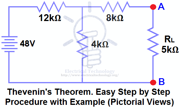
Solution:-
STEP 1.
Open the 5kΩ load resistor (Fig 2).
STEP 2.
Calculate / measure the open circuit voltage. This is the Thevenin Voltage (VTH) as shown in Fig (3).
We have already removed the load resistor from Fig. 1, so the circuit becomes an open circuit, as shown in Fig. 2. Now we need to calculate the Thevenin voltage.
Since a current of 3mA of current flows through both the 12kΩ and 4kΩ resistors (they are in series), no current flows through the 8kΩ resistor because it is an open circuit.
The voltage drop across the 4kΩ resistor based on V = I × R is:
3mA × 4kΩ = 12V
We also know that the 8kΩ resistor is in parallel with the 4kΩ resistor. In parallel branches, the voltage is the same, so the 8kΩ resistor will also have 12V across it. Therefore, 12V appears across terminals A and B, i.e.:
VTH = 12V

STEP 3.
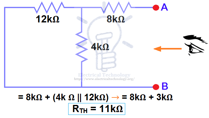
Open all current sources and short all voltage sources, as shown in Fig. 4.

STEP 4.
Calculate / measure the open circuit resistance. This is the Thevenin Resistance (RTH).
We have removed the 48V DC source to zero by replacing it with a short circuit in Step 3 (as shown in Fig. 3). We can see that the 8kΩ resistor is in series with the parallel combination of the 4kΩ resistor and the 12kΩ resistor, i.e.:
8kΩ + (4k Ω || 12kΩ) ….. (|| = in parallel with)
RTH = 8kΩ + [(4kΩ × 12kΩ) / (4kΩ + 12kΩ)]
RTH = 8kΩ + 3kΩ
RTH = 11kΩ
STEP 5.
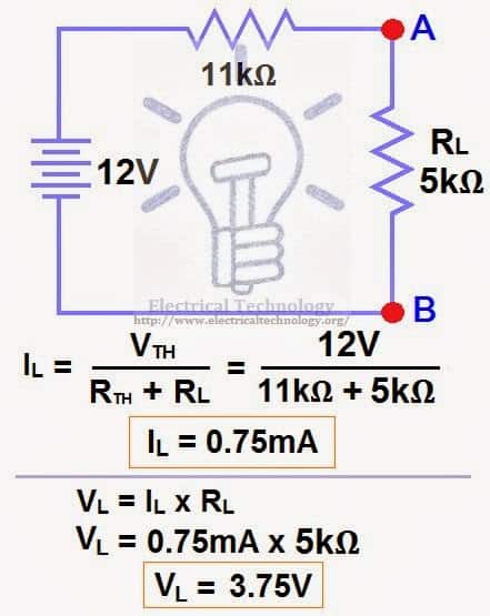
Connect the RTH in series with voltage source VTH and re-connect the load resistor. This is shown in fig (6) i.e. Thevenin circuit with load resistor. This is the Thevenin’s equivalent circuit.

STEP 6.
Now, apply the last step i.e. Ohm’s law . Calculate the total load current and load voltage as shown in fig 6.
IL = VTH / (RTH + RL)
IL = 12V / (11kΩ + 5kΩ) → = 12/16kΩ
IL = 0.75mA
And
VL = IL × RL
VL = 0.75mA × 5kΩ
VL= 3.75V
Now compare this simple circuit with the original circuit shown in Figure 1. Do you see how much easier it becomes to measure and calculate the load current in a complex circuit or network for different load resistors using Thevenin’s Theorem? Yes! and only yes.
- Related Posts:
- Maximum Power Transfer Theorem for AC & DC Circuits
- Kirchhoff’s Current & Voltage Law (KCL & KVL) | Solved Example
- Compensation Theorem – Proof, Explanation and Solved Examples
- Substitution Theorem – Step by Step Guide with Solved Example
- Millman’s Theorem – Analyzing AC & DC Circuits – Examples
- Superposition Theorem – Circuit Analysis with Solved Example
- Tellegen’s Theorem – Solved Examples & MATLAB Simulation
- SUPERNODE Circuit Analysis | Step by Step with Solved Example
- SUPERMESH Circuit Analysis | Step by Step with Solved Example
- Voltage Divider Rule (VDR) – Solved Examples for R, L and C Circuits
- Current Divider Rule (CDR) – Solved Examples for AC and DC Circuits
- Star to Delta & Delta to Star Conversion. Y-Δ Transformation


thanks, good easy to understand.but the voltage source have more than one. how to do it.
It is simple example for ref & explanation purpose only…Wait for upcoming posts….Thanks
Surely when the load resistor is replaced the circuit changes and the 8k and 5k are in parallel with the 4k causing the cu
Surely when the load resistor is replaced the circuit changes and the 8k and 5k are in parallel with the 4k causing the current and voltage to change oops just figured it out the long way and the 5k gets 3.75 out of the 9.75 volts across that part of the circuit your way of showing thevenin is better thank you
Thanks for your kind words…
the example is clear compare it to the lectures example
If the voltage source is more than one you calculate two components of Nortons current that is I’ and I”, add them to get the total Nortons current and repeat the procedure explained above.
Admin. You are doing great work. Your posts related to electricals are easy to learn. . . Keep updating. . .
Thanks for appreciation…
Thevenin's Theorem is not very intuitive for a newbie, good to have this nice easy to follow explanation.
simple and good steps for easy understanding
Good one for basic understanding of theorems :)<br />
How did u get 3mA?
I = V / R …<br />= 48V / (12kΩ + 4kΩ )<br />= 3mA <br /><br />So 3mA Current will flow in both 12kΩ and 4kΩ resistors as this is a series circuit because current will not flow in the 8kΩ resistor as it is open<br /><br />
If the rounded off value of 3mA is used to find Vth you get 12V.
If the less rounded off value of 3.273mA is used we’d get 13V.
when the load terminals are open then all the current passes through only first circuit and the current is from v=i/r can be calculated
1st of all find req than by v=ir , i=v/r we can get the value of current
48Volts divided by 16kilo-ohmns
Thanku. <br />What happens when there is 2 voltage sources?
Use Kirchhoff law
i am proud that u can make this subject such intresting..<br /><br />hope many teachers of ur kind should be there..<br /><br />i am learning this during my job period ..if it was during my college it would have been a big deal for me..<br /><br />anyway thanks!!
Thanks for your kind words…
hope many teachers of ur kind should be there..<br /><br />i am learning this during my job period ..if it was during my college it would have been a big deal for me..<br /><br />anyway thanks!!
Thank you
Dhuurrrrrr!!
tq admin..mechanical stdent frm malaysia :)
Most welcome dear….
How can I find you in Facebook?
Here is the official Facebook Page of Electrical Technology.
step by step process is easy way for students to understand the problem
Great job there, sometimes is easy to understand through other source.
thank you sir…. this is really a helpful information..
thank u very much sir……
plesae provide telligan’s theorem
Thanks for your very informative post. I had a very bad going with this topic, but now I can assure keep my hands dirty on complex circuits related to this phenomenon by using your idea.
outstanding sir
it is very easy to understand the concept,but if more than one voltage sources are present then how will be the solution and procedure
It is too much easy
boss i love this your tutorials its the best i have ever seen you simplified the sturf to the last five star 4 u *****
best tutors site
Thank you…
sir this is awesome sir
i had clarify my doubts succesfully
it is soo easy to understand
Thank you very much!!!
could you give another exercise with 2 suppliers? and show steps
Thumps up to yo tutorials,now I understand the theorem way better than I previously did.Thanx so Much
Thanks for appreciation….
why you solve 12 and 4 as parallel?
If you see in step 4, 8kΩ resistor is in series with a parallel connection of 4kΩ resistor and 12k Ω resistor.
i.e. If you solve for the parallel connection of 4kΩ resistor and 12k Ω, It becomes in Series with 8kΩ.
In step 2, The Circuit is Open, Hence, Current will not flow in 8kΩ, Therefore, That’s Why it is in parallel with 4kΩ.
will you please add step by step procedure for dual loops that will help alot
Thanx in advance
Great job. you make the determination of thevenin’s voltage is very very easy. Thank you…
I could not solve even a single problem .But this helped me a lot .Thank u
Glad it helps You….
Thanks…
can i get more relevant problems using thevinin’s theorem & may i know that thevinin’s theorem can use for AC supplied circuits.
Yes…. It can be used on both AC and DC Circuits,,, We will post about Thevinin’s theorem about AC Circuits in coming days… Thanks
Told how to solve thevinins them in ac by using kvl.
please inform more and more about electrical and electronics
sir I have a confusion when you calculate Rth because I dont think that Rth=8+4||12. But It should be Rth=12+4||8. Am I wrong Sir ?, if so then please guide me.
Thanks
Ankit
Hi Ankit,
As mentioned above that We can see that 8kΩ resistor is in series with a parallel connection of 4kΩ resistor and 12k Ω resistor. i.e.:
8kΩ + (4k Ω || 12kΩ)
Saqib Javeed is Right…. Thanks
let me know if you want to know more… Thanks
simply superb
Thank you very much,
this was the best explanation available on the internet
Thanks for appreciation …
Was very helpful…thanks a billion times ?
Most Welcome….
Awesome explanation. It’s very useful to us, Thank you!!
Most welcome… And thanks for appreciation….
have we already been provided with 3Am or you have solved it? if you have solved it how have you done it?? a ain’t sure if I have followed you on that one
It is not provided.
In Step 2, You may see that this is an Open Circuit, I.e. Current will not flow in the 8kΩ.
So the circuit of 48V, 4kΩ and 12kΩ becomes a series circuit.
By using Ohms Law, (I = V/R), We found the value of current as 3mA.
Thanks
what will be total R in the circuit if 4k shud the load resistance in revolving towards the source
You may just change the value of the resistance and solve again same as above…. No Difficulties…. :)
you said 8k resistor is parallel to 4k resistor in step 2.in step 4 you said 8k resistor is sereis to 4k.why?
Yes Dear…. If you see in step 4, 8kΩ resistor is in series with a parallel connection of 4kΩ resistor and 12k Ω resistor.
i.e. If you solve for the parallel connection of 4kΩ resistor and 12k Ω, It becomes in Series with 8kΩ.
In step 2, The Circuit is Open, Hence, Current will not flow in 8kΩ, Therefore, That’s Why it is in parallel with 4kΩ.
Thanks.
let me know if you want to know more… Thanks
wow. thank you. now i understand. :)
thank you for this. but how about 3 sources using this theorem?
Please how was the 3mA current gotten ?
can you explain to me about how did you get 12V as it is 48V?
IT IS GOOD BUT I WILL LIKE IT IF IT SOLVED USING SMALL NUMBERS LIKE 3,4,2 TO MAKE IT LOOK MORE SIMPLER
Thevenin made simply. thanks dear.
A/C to my point of view, Its very simple and easy method for understanding..
Simplified example…great work
if I find current across 5 ohm resister there is a greater value then the total load current that is 0.75 can anyone answer
thanks for the example.
thank you dear
A really Understanding work!
Thanks for keeping the simplicity in the explination I thoroughly understood the conpect.
Thanks soooooo much, it really help me out.
Thank you so much to help me in easy way
And if there is an ammeter in parallel with the resistance, then what to do
Really good
thnks sir
If there are a voltage or current source between A & B terminals or in the place of load resistor, Then how can i solve this????????
VERY SIMPLY AND THOROUGHLY EXPLAINED THE CONCEPT OF THEVENINS THEOREM. PLEASE INCLUDE THE NOTES OF TWO POLE NETWORKS ALSO
Am happy for the steps of thevenins i cam now calculate but following the steps
sir please tell me….is this the right and only method to solve problems by thevenin’s theorem?
Yes! But you can analyze the same problem by different methods as well.
can you please tell me the different methods sir?
please respond quick!!
Very good explanation. I tend to solve complex circuits using Kirchoff’s laws…Are there particular cases when one method is favourably used instead of the other? ( I have not read all posts…maybe you have already gone into this)
how did u get 3mA
3mA current will flows in both 12kΩ and 4kΩ resistors as it is a series circuit because current will not flow in the 8kΩ resistor as it is open (Fig 2)
thankyou its help full.
request.. how can I calculate if there are voltage source in the circuit?
thank u so much
Where does the load resistor come from? Can any load resistor be used?
Hi Admin
If point A and point B are at 4kohm, how to get V(TH) and R(TH)?
Thanks
Sir RL=5kom kese find ?
It is the given data in the first circuit (fig 1).
Sr i need more explanation on how you get 12v
Inspiring lessons,
Thanks so much