What is Negative Feedback Amplifier Systems ?
Negative Feedback Op-Amp and Non-Inverting Operational Amplifier Circuit
1. What is a Feedback?
Feedback is considered an essential part of our lives. Try to close your eyes and touch your fingers together, the first time you make it you may not succeed because you have broken a feedback loop that normally regulates your motions.
in electronics engineering, Amplifier feedback loops are used to control the output of electronics devices where, the output signal is used as input signal.
The regulatory role of feedback shows itself in Electronic, biological and mechanical systems, allowing accurate realization of functions.
we will try to introduce the general negative feedback structure More specifically, we will concentrate on the negative feedback amplifier.
2. The Negative Feedback Amplifier:
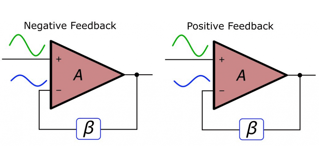
in simple words, A feedback said to be negative feedback if the output signal is opposite in value or phase (i.e. out of phase or anti phase) to the input signal.
The word amplifier here is slightly misguiding, this structure is not limited to only increasing the amplitude of a signal. This amplifier can be a unity gain system (A=1) that is used to improve a circuit’s input or output impedance, or it can be a filter that passes certain frequencies while blocking the others.
2.1-The Generic Feedback Amplifier Block Diagram
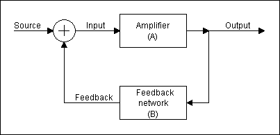 By subtracting the actual output value multiplied by the feedback β from the source signal and using the subtraction result as the input to the open loop amplifier (A), we can accurately control the output, even when the input to the output relationship is complex.
The parameters here are A and β, So what exactly A and β are?
A: is the open loop amplification that the overall system would be applied in the absence of feedback.
β: is the feedback factor that determines how much of the output signal is fed back to the subtraction node to be subtracted from the source. This should become more and more clear when you think in terms of a basic non-inverting op amp circuit:
2.2- The Non-Inverting Op-Amp Circuit:
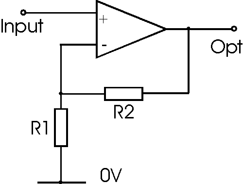
The two resistors (R1 and R2) that we use to control the gain are no more than a divider network that returns a percentage of the output to the the op-amp specifically the inverting terminal of the op-amp.
The voltage across the output resistance is expressed by the ratio of R1/(R1 + R2) which is (B), multiplied by the voltage across the resistance pair. So, the percentage of output fed back and subtracted from input -i.e., the feedback factor β is R1/(R1 + R2). It is worth to get a good understanding of this concept, because β will be the dominant factor when we discuss stability.
- Related Post: Quantization & Sampling? Types & Laws of Compression
3- Notes about Gain (A) and Feedback Factor (β):
They needn’t to be constants as in A = 105 and β = 0.01. They can also represented as a function of frequency, it means that the value of A or β varies according to the frequency of the input signal passing through the amplifier (in other word frequency dependent).
3.1- Feedback Equations:
Now we will briefly explain some relationships and formulas that will help for further understanding the behavior of the feedback amplifier. First is the mathematical formula of the feedback factor β: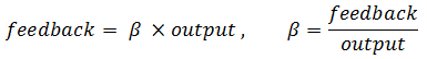
This is simply a relation between and the output. Next is a direct relation between the input and the output,
output=A ×input
3.2- Negative Feedback Equations:
Another more interesting relation is the equation of the closed loop gain (GCL), i.e., the overall gain of the amplifier when negative feedback exist.

This relationship is very simple, In feedback amplifier applications, the term Aβ (referred to as the open loop gain) is larger than 1.
for example, with an open loop op-amp gain of 105 and a feedback factor(β) of 0.01, the loop gain is 103. By further approximation we can simplify the closed loop gain expression as follows: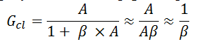
And here we see from the previous equations that the gain (Gcl) ( depends only on β. recall the non-inverting op-amp circuit shown above, also we recall that the gain equation for a non-inverting amplifier (GNI) is 1 + (R2/R1):
4- Improving Bandwidth and Gain Sensitivity:
4.1- Improving Sensitivity:
We have already mentioned the feedback’s ability to make an amplifier dependent on β instead of A, so
Here we will discuss that the closed loop gain plus the feedback circuit is much less sensitive to variations in the open loop gain.
there is another thing that we have not yet explicitly discuss is that greater desensitization is achieved when the open loop gain is larger and the closed loop gain is smaller. Recall the equation of the closed loop gain.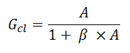
We can clearly see that any change in A is divided by the term (1 + Aβ) before it affects the closed loop gain. With a slightly little mathematics, you can prove that the ratio GCL,old/GCL,new is reduced by the factor (1 + Aβ) if compared to Aold/Anew. so, when gain A is very large, as it is in standard op-amps, and β is limited to standard values for example, not less than 0.01, corresponding to a gain of 1000, the term (1 + Aβ) is large enough to be sure that the closed loop gain isn’t greatly affected by variations of A.
4.1.1- Example on Improving Sensitivity Op-Amp:
For example, let us say that the open loop gain of an op-amp increases or decreases by 10 % as a result of changes in temperature for example, with an open loop gain of 100,000. The feedback network is designed for a gain of 10.
It is safe to say that most systems would not be greatly affected by a 0.00009 V/V increase or decrease in amplifier gain.
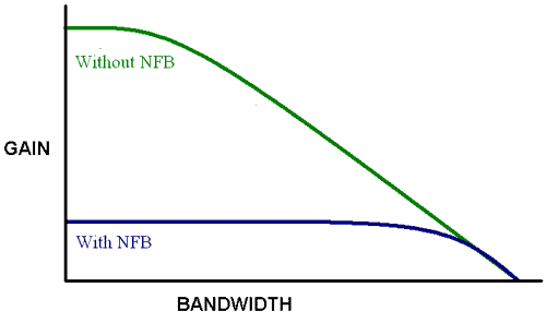
4.2- Improving Bandwidth of Op-Amp:
As mentioned before, real amplifiers don’t have a single value of gain that applies to signals of any frequency. Most op-amps are compensated internally to make them more stable, resulting in a decrease of 20 dB/decade for the open loop gain starting at very low frequencies. And even in the devices that are designed for high frequency operation, parasitic capacitances and inductances will eventually cause the gain to roll off. So with negative feedback you can overcome this bandwidth limitation.
For the reason that the we are considering the frequency response of the amplifier, we have to modify the closed loop gain equation as follows, where GCL,LF and ALF denote the closed loop and open loop gain at much lower frequencies than the open loop cutoff frequency.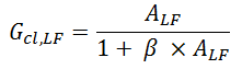
The interesting thing here is what happens to the frequency response, if you plot and analyze the closed loop gain as a function of frequency, you will obviously find that the closed loop cutoff frequency (fC,CL) is related to the open-loop cutoff frequency (fC,OL) as follows:![]()
so, we actually get more usable bandwidth in the amplifier plus the feedback circuit. Note also that as with gain desensitization, higher open loop gain leads to more improvement in bandwidth.
4.2.1- Gain Vs Bandwidth of Amplifier
You might have noticed something interesting here, the bandwidth is increased by the factor (1 + ALFβ) and the low frequency gain is decreased by the factor (1 + ALFβ). This leads to the result that decreasing the gain of the amplifier by a certain factor causes an increase in the bandwidth by the same factor.
Related Posts:


Great site. Good bit of info here.. very informative
Thank you
Why negative feedback used in control system
In the first image there is an error with signs of opamp.
Why negative feedback used in control system
i would like a dieagram to wireing up q 3phase moterto run off a 220v if you can helpme out if you can. jim