Smart Home Automation System Project using Arduino
Automation (such as home automation and industrial automation etc) has become important in today’s world as it helps to complete a task with lesser human assistance and in a smarter way. Houses are becoming smarter and developed these days with the help of automation devices.
Home electrical appliances are using remote-controlled switches rather than conventional switches. In today’s world, most of the people have access to smartphones and its use have become very popular and essential in our lives.
We can use smartphones to control the household appliances with just one click or one message. With the help of controllers and communication devices home appliances can be remotely controlled. In this project, we will use the Arduino UNO board for the development of Smart Home Automation project with the HC-05 Bluetooth module which is remotely controlled by a smartphone.
It can be really helpful for the paralyzed people who cannot do their work on their own and such devices can become a great help for these people.
- Related Post: Voice Recognition Based Home Automation System
Components Required
- Arduino UNO
- HC-05 Bluetooth Module
- Relays
- Jumper wires
- Light Bulbs
- Bluetooth Terminal HC-05 App (Download from play store)
Arduino UNO
Arduino is an open-source platform which is used to develop electronics projects. It can be easily programmed, erased and reprogrammed at any instant of the time. There are many Arduino boards available in the market like Arduino UNO, Arduino Nano, Arduino Mega, Arduino lilypad, etc with having different specification according to their use.
In this project, we are going to use Arduino UNO to control home appliances automatically. It has ATmega328 microcontroller IC on it which runs on 16MHz clock speed. It is a powerful which can work on USART, I2C and SPI communication protocols. This board is usually programmed using software Arduino IDE using a micro USB cable.
ATmega328 comes with preprogrammed onboard boot loader which makes it easier to upload the code without the help on external hardware. It has vast application in making electronics projects or products. The C and C++ language is used to program the board which is very easy to learn and use. Arduino IDE makes it much easier to program. It separates the code in two parts i.e. void setup() and void loop().
The function void setup() runs only one time and used for mainly initiating some process whereas void loop() consists the part of the code which should be executed continuously.
This model consists of 6 analog input pins and 14 digital GPIO pins which can be used as input-output, 6 of which provides PWM output and analog using pinMode(), digitalWrite(), digitalRead() and analogRead() functions.
6 analog input channels are from pins A0 to A5 and provide 10-bit resolution. The board can be powered either from using a USB cable which operates at 5 volts or by DC jack which operates between 7 to 20 volts. There is an onboard voltage regulator to generate 3.3 volts for operating low powered devices.
Since the ATmega328 work on USART, SPI and I2C communication protocol, has 0 (Rx) and 1(Tx) pins for USART communication, SDA (A4) and SCL (A5) pin for I2C and SS (10), MOSI (11), MISO (12) and SCK (13) pins for SPI communication protocol. These specifications make Arduino Uno board perfect for Home Automation project.
HC-05 Bluetooth Module
HC-05 is a Bluetooth module used for wireless communication. It is used mostly to establish serial two-way wireless communications between microcontrollers, smartphones, computers, sensors, etc. The range of this Bluetooth module is less than 100 meters and also depends on atmospheric conditions.
It works on the USART (Universal Synchronous Asynchronous Receiver Transmitter) protocol to communicate with other devices. It can work both in master and slave mode with supported baud rates 9600, 19200, 38400, 57600, 115200, 230400 and 460800. By default, it works on slave mode and master mode can be configured using AT commands.
It can be used to transfer data both ways from a microcontroller to any device and device to a microcontroller. HC-05 Bluetooth module works in command mode and data mode. Command mode is used to access the configuration setting of HC-05 using some AT commands and Data mode is used to send the data serially. Command mode can be accessed by grounding the “key” pin and using AT commands we can change its setting.
There are AT commands which can be used to change the name, password, baud rate, etc. of the module. Here are few AT commands:
- AT – for checking if the module is communicating or not
- AT+NAME = hc-05 – for changing the name of the device to “hc-05”
- AT+PSWD = 1234 – for changing the password to 1234
- AT+UART = 9600, 1, 0 – for changing the baud rate to 9600, stop bit to 1 and parity bit to 0.
Related Project: Automatic LED Emergency Light Circuit using LDR
Pin Out of HC-05:
EN/Key pin: This pin is used to set Bluetooth module in either command mode or data mode. Command mode can be accessed by setting this pin high and data mode can be accessed setting it low. By default, it is set as low in data mode.
- VCC: This is the power supply pin which is connected to either 5V or 3.3V.
- Ground: This is the ground pin of the Bluetooth module.
- TXD: This pin used for serial transmission of the data.
- RXD: This pin is used for serially receive the data.
- State: This pin tells whether the module is connected or disconnected with the other device.
| Pin on HC-05 | Description |
| EN/key | High – Command Mode, Low – Data Mode |
| VCC | 3.3 V to 5 V |
| GND | Ground |
| TXD | Transmit Serial Data |
| RXD | Receive Serial Data |
| State | Shows module connected or not |
In this project, HC-05 is used to establish serial wireless communication between Arduino Uno and Smartphone. This can be done by connecting Hc-05 with the Arduino Uno and installing an application on the smartphone. Although there are various applications available for connecting a smartphone to HC-05. But here we are going to use Bluetooth Terminal HC-05 which can be downloaded from the play store.
Connect the HC-05 with Arduino UNO as given in the circuit diagram. TXD pin of HC-05 goes to RX (pin 0) of the RXD pin of HC-05 goes to TXD (pin 1) of the Arduino Uno. EN/key is set as LOW. Turn on the Bluetooth of your smartphone and search for Bluetooth devices. Connect to the Bluetooth device named as “HC-05”. By default password is either “0000” or “1234”.
HC-05 Bluetooth module has built-in red led which indicates the connection status. Before any connection it blinks continuously in some periodic manner and after it gets connected its blinking speed slows down.
Application of HC-05 Bluetooth module:
- Computer and peripheral devices
- GPS receiver
- Industrial control
- Microcontroller projects
Relay
A relay is an electromagnetic switch which is operated by a small electric current to turn on or off one or many bigger circuits. It consists of an electromagnet coil which converts in a temporary magnet when a small electric current is passed through it.
A relatively small current is used to create a magnetic field in a coil with a core and this is used to operate a switch that can control a much larger current. Earlier relays were used in telegraphs and telephone exchanges to amplify the signals.
After the invention of computers relays were used to perform Boolean and logical operations. Relays come in different sizes and varieties according to their use in circuits. The main applications of the relay include motor control, automotive applications, industrial applications, home automation, etc.
In this project, we are going to use an electromagnetic relay to turn on and off the home appliances like tube light, bulb, fan or any ac powered source in our home by giving DC signals from the Arduino UNO.
The relay has 6 pins, two of which VCC and Ground are used to give power to the relay. One pin is the Data pin which is used to take the signal either “1” or “0” from microcontrollers. Other 3 pins Normally Closed (NC), Common, Normally Open (NO) are used to connect AC powered appliances. This relay works in two conditions either in Normally Open or in Normally Close condition:
Normally Open: It closes the circuit whenever the relay is activated and it opens the circuit whenever the relay is deactivated.
Normally Close: It opens the circuit whenever the relay is activated and it closed the circuit whenever the relay is deactivated.
- Related Project: Automatic Night Lamp Using Arduino and LDR
Pinout of Relay:
| Pin on RELAY | Description |
| VCC | 5V |
| GND | Ground |
| Data pin | “1” or “0” from microcontroller |
| NC | For Normally Closed Circuit |
| COM | Common |
| NO | For Normally Open Circuit |
Applications of the relay:
- Relay is used to provide safety-critical logic.
- They are used to control a high voltage circuit with a small voltage signal.
- Relays are also used for protection purpose.
- Relays are used in substation and grids when supplying electricity from one point to another.
Related Project: Automatic Street Light Control System using LDR
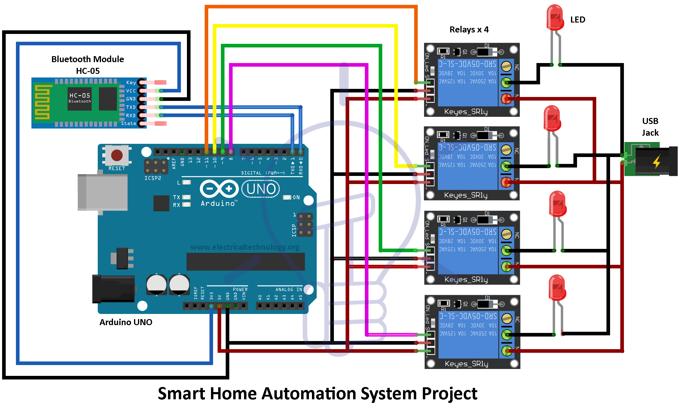
Circuit Diagram
The circuit is designed using Arduino, Bluetooth, relay, and LEDs. We have connected the Bluetooth serially with the Arduino. The Relay is used to operate the home appliances. We have used four relays for four appliances. You can change the numbers of the relay to operate various home appliances accordingly. While moving to the hardware, the LEDs will be replaced by Bulbs.
The command for controlling the home appliances will be sent through a “Bluetooth terminal HC-05 app” from your smartphone to the Bluetooth, connected to the Arduino. Then Arduino read the data coming serially to the Bluetooth. Hence, actions are performed according to the command coming from the Bluetooth to the Arduino.
- Related Project: Traffic Light Control Electronic Project using IC 4017 & 555 Timer
Working of Arduino based Home Automation
Make the connection for Home Automation project as given in the circuit diagram. First of all, we connect the bulb with AC powered sources and with relays as given in the circuit diagram. Then the relays are given DC power from the Arduino Uno board.
Data pins of the relays are connected at pins 8, 9, 10 and 11 to the Arduino which are the output pins of Arduino. Then connect the HC-05 module with the Arduino Board as shown in the diagram and power the Adruino Board. Upload the code given at the end of the project using Arduino IDE.
Turn on the Bluetooth in your smartphone and connect the HC-05 module by entering the password. By default, the password is “0000” or “1234”. After successfully connecting your smartphone with the HC-05, Open “Bluetooth terminal HC-05 app in your smartphone” and it will show your device connected to HC-05. Now send the data “Bulb1 turn on” or “Bulb2 to turn off” to turn on or off any bulb. This is how you can control the lights in your home remotely.
- Related Project: Clap Switch Circuit Electronic Project Using 555 Timer
Project Code
#include

int bulb1 = 8;
int bulb2 = 9;
int bulb3 = 10;
int bulb4 = 11;

SoftwareSerial bt(0,1); /* (Rx,Tx) */

String str;

void setup() {
bt.begin(9600);
Serial.begin(9600);

pinMode(bulb1,OUTPUT);
pinMode(bulb2,OUTPUT);
pinMode(bulb3,OUTPUT);
pinMode(bulb4,OUTPUT);

}

void loop() {

if (bt.available())
{
str = bt.read();
Serial.println(str);
//bulb1
if(str=="bulb1 on")
{
digitalWrite(bulb1,HIGH);
Serial.println("BUlB 1 is ON");
}
else if(str=="bulb1 off")
{
digitalWrite(bulb1,LOW);
Serial.println("BUlB 1 is OFF");
}
else
{
digitalWrite(bulb1,LOW);
}
//bulb2
if(str=="bulb2 on")
{
digitalWrite(bulb2,HIGH);
Serial.println("BUlB 2 is ON");
}
else if(str=="bulb2 off")
{
digitalWrite(bulb2,LOW);
Serial.println("BUlB 2 is OFF");
}
else
{
digitalWrite(bulb2,LOW);
}
////bulb3
if(str=="bulb3 on")
{
digitalWrite(bulb3,HIGH);
Serial.println("BUlB 3 is ON");
}
else if(str=="bulb3 off")
{
digitalWrite(bulb3,LOW);
Serial.println("BUlB 3 is OFF");
}
else
{
digitalWrite(bulb3,LOW);
}
//bulb4
if(str=="bulb4 on")
{
digitalWrite(bulb4,HIGH);
Serial.println("BUlB 4 is ON");
}
else if(str=="bulb4 off")
{
digitalWrite(bulb4,LOW);
Serial.println("BUlB 4 is OFF");
}
else
{
digitalWrite(bulb4,LOW);
}

}
}
Programming Code Explanation
Include the libraries required for the project, SoftwareSerial.h library is imported for serial communication with Bluetooth Module HC-05.
#include<SoftwareSerial.h>
Declaration of variables of output pins of Arduino at 8, 9, 10 and 11 which goes to data pin of each of the four relays. Variable string “str” stores the data we get from smartphone using HC-05 Bluetooth Module.
int bulb1 = 8;
int bulb2 = 9;
int bulb3 = 10;
int bulb4 = 11;
String str;
pinMode(bulb1,OUTPUT);
pinMode(bulb2,OUTPUT);
pinMode(bulb3,OUTPUT);
pinMode(bulb4,OUTPUT);
Bluetooth serial communication and serial monitor are initiated at 9600 baud rate.
bt.begin(9600);
Serial.begin(9600);
If the data got from the smartphone using Bluetooth Module HC-05 is “bulb1 on” then we turn on the bulb 1 by setting data pin of the relay as HIGH. If data is “bulb1 off” then we turn off the bulb by setting the data pin of the relay as LOW. If no data received for bulb 1 then we set our bulb 1 to LOW. The same thing is done for bulb 2, bulb 3, bulb 4.
if(str==”bulb1 on”)
{
digitalWrite(bulb1,HIGH);
Serial.println(“BUlB 1 is ON”);
}
else if(str==”bulb1 off”)
{
digitalWrite(bulb1,LOW);
Serial.println(“BUlB 1 is OFF”);
}
else
{
digitalWrite(bulb1,LOW);
}
Hence, you can control any home appliance in your home by using Arduino UNO, Bluetooth, and relay. We have also provided the technical information for the components required for constructing this project. The circuit diagram consists of LEDs which will be replaced by the AC bulbs used in the home.
Related Projects:
- Automatic Plant Watering & Irrigation System – Circuit, Code & Project Report
- Rain Alarm Circuit – Snow, Water and Rain Detector Project
- Water Level Indicator Circuit Diagram- Two Simple Projects
- More Electrical & Electronics Engineering Projects
-
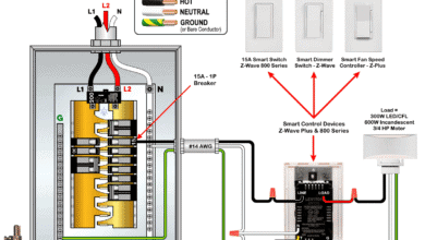 Wiring Z-Wave Smart Switch, Dimmer & Fan Speed Controller
-
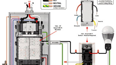 How to Wire a Smart Switch in a 120/240V Load Center
-
 How to Wire 15A and 20A Wi-Fi Smart GFCI Outlets
-
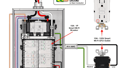
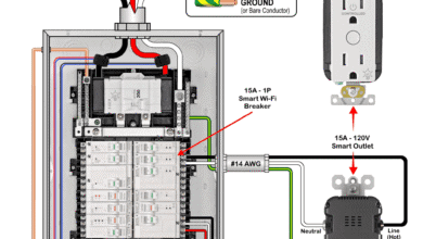 How to Wire a 15A Wi-Fi Smart Outlet in a Smart Panel
-
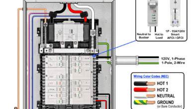 How to Wire Smart AFCI/GFCI Breaker in a Smart Load Center
-
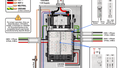 How to Wire a Smart GFCI Breaker in a 120/240V Smart Panel