Water Level Indicator Circuit Diagram- Two Simple Projects
Water Level Indicator Circuit – Liquid Level Sensor with Alarm
Overflow of water is definitely a major problem nowadays. Overflow water tanks eventually lead to loss of water and natural resources as well. Are you looking for an electronic solution to resolve this issue? Are you looking for an automated device to solve this problem? If yes, then here is your halt. In this article, we will be discussing the water level indicator circuit which informs you about the different levels of water in the water tank or container. The circuit is designed so that the buzzer will start beeping once the water tank is completely full. You can also use this device to sense the water level at a determined level. This device is capable of eliminating the manual method of checking water levels of the tanks at a regular time interval.
Using this water level indicator device, you can easily measure the different levels of water in the water tank so that you can turn the motor OFF and ON accordingly. No doubt, this circuit can be designed using various controllers and transistors. In this project, we will be discussing the design of a water level indicator circuit using two methods. In the first circuit, we are using the BC 547 transistor as the main part and in the second circuit, ULN2003 IC is playing the major role.
Water Level Indicator Using BC 547 Transistor
Before starting to design the circuit, gather the following components according to the given specifications.
- Transistor – BC 547
- Resistors- 6, 330 Ohm
- LEDs- 3
- Buzzer
- Battery- 5-9 V
Circuit Diagram
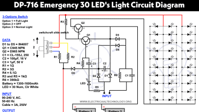
BC 547 is an NPN bipolar junction transistor that is used to amplify current to a certain level. Here, we have used BC 547 as a Switch. We have created three different levels of water level detection namely A, B, and C. We have connected LEDs at three points to indicate particular water level along with a buzzer to indicate the full level of the tank. Whenever water level reaches point A, transistor Q1 is turned ON and Red LED starts glowing. When the level of water reaches to point Transistor Q2 is turned ON and the yellow LED starts glowing. Similarly, when the water level reaches to point C, Transistor Q3 is turned ON which triggers the White LED and the buzzer starts beeping indicating that tank is full, you can turn off the water pump. We can create different levels of water detection using more colored LEDs and transistors to sense the desired level of water in the tank.
- Related Project: Smart Irrigation System – Circuit Diagram and Code
By doing some modification, we can even control the ON/OFF operation of the water pump.

Working
In this circuit, the BC547 is used as a Switch. We have attached resistors of 220 Ohm at the base of transistors Q1, Q2 Q3 to avoid the transistor from being destroyed from high current across the LEDs. When no voltage is applied at the base of transistors, there is no current flowing through the collector and emitter terminal of the Transistor. In result, LED will remain OFF.
When the water level reaches the point A, a conductive path is created between the base of transistor Q1 and the positive terminal of the battery. Therefore, the positive side of battery and base of the transistor Q1 gets connected with each other. As soon as the positive voltage is applied at the base of transistor Q1, the transistor Q1 is turned on and the RED LED starts glowing.
Similar to the above process, a conductive path is formed between the base of transistor Q2 and the positive terminal of the battery, as soon as the water level reaches point B. A positive voltage is applied at the transistor which turns ON the yellow LED.
As the water level reaches to point C, the Transistor Q3 is turned ON due to the conductive path created and a positive voltage is applied at the base of it. This turn ON the white LED and the buzzer connected to the transistor Q3. This indicates that the container is full.
BC 547 is known as cheap and easy to use transistor which can be used to design a low-cost water level indicator. You can use this device in day to day life to detect the various levels in water in a container.
Water Level Indicator Circuit Using ULN2003 IC
We can design the water level indicator circuit using ULN2003 IC as the main component. Before starting the design process of this circuit, let’s give you a brief explanation of the ULN 2003 IC.
ULN2003 IC
ULN 2003 IC belongs to the family of ULN 200X series if ICs. It is a monolithic IC consists of seven NPN Darlington transistor pair. Generally, this IC is used in 5V TTL CMOS devices. This IC consists of common cathode clamp diodes for each NPN Darlington pair. This makes the ULN 2003 IC suitable for switching inductive loads.
Pin Diagram:
Go through the table to understand the pinouts of the ULN 2003 IC.
| Pin No. | Function | Name |
| 1 | Input for 1st channel | Input 1 |
| 2 | Input for 2nd channel | Input 2 |
| 3 | Input for 3rd channel | Input 3 |
| 4 | Input for 4th channel | Input 4 |
| 5 | Input for 5th channel | Input 5 |
| 6 | Input for 4th channel | Input 6 |
| 7 | Input for 3rd channel | Input 7 |
| 8 | 0V | Ground |
| 9 | Freewheeling diodes | Common |
| 10 | Output for 7th channel | Output 7 |
| 11 | Output for 6th channel | Output 6 |
| 12 | Output for 5th channel | Output 5 |
| 13 | Output for 4th channel | Output 4 |
| 14 | Output for 3rd channel | Output 3 |
| 15 | Output for 2nd channel | Output 2 |
| 16 | Output for 1st channel | Output 1 |
Each Darlington pair in ULN 2003 IC is rated at 500 mA and withstanding current of 600 m A. Each driver consists of a diode to dissipate the voltage spikes while driving the loads.

Applications of ULN 2003 IC:
ULN 2003 is generally used in high voltage current applications that include:
- Relay drivers
- Stepper motors
- LED lamp drivers
- Logic buffers
- Hammer drivers
Collect the below-mentioned components to design the water level indicator using ULN 2003 IC.
- ULN 2003 IC
- LEDs – 3 different colors
- Resistors – 3 (1 k ohm each)
- Buzzer
- Connecting wires
Circuit Diagram:
Arrange the components as shown in the picture. We can use the three different colored LEDs to create three detection levels. Connect three 1K resistors to the pin 15, 13 and 10 of ULN 2003 IC, as shown in the circuit diagram. Connect the pin 7, 4 and 2 of ULN 2003 IC to create three different levels in the water container. Connect pin 8 of the IC to ground and pin 9 to a 12-volt power supply.
Working:
When the water level reaches point A, a conductive path is created between the positive terminal of the battery and input pin 2 of the ULN 2003 IC. In result, output pin becomes high and the Red LED starts glowing, this indicates that the water in the tank is not filled and the motor pump needs to be turned ON.
Similarly, as soon as the water level reaches to point B, input pin 4 of the ULN 2003 IC becomes high and output pin 13 is activated. In result, the yellow LED starts glowing. This indicates that the tank is half filled.

Similar to the above process, as soon as the water level reaches point C, pin 7 of ULN 2003 IC becomes high and output pin 10 of the ULN 2003 IC is activated. In result, green LED is turned ON. Finally, as soon as the water level reaches point D, output pin 10 of ULN 2003 IC is activated. In result, the buzzer starts ringing. This indicates that the water container is full and you can switch OFF the motor pump.
Features of Water Level Indicator Circuit:
- Consumes very little power
- Low maintenance and easy installation
- Compact and portable design
- Fully automated saves manpower
- You can change the water levels as per your choice
Applications:
Water harvesting is one of the most important tasks. Sometimes, due to the overflow of water tanks, a large amount of water is wasted. In the world full of machines, everyone is dependent on machines to ease their work. So, for an automated and electronic solution to this problem, you can use this cheap and easy to use water level indicator device to detect the water levels at a determined point.
- By doing some modification and attach the motor with the circuit, we can turn ON/OFF the water pump automatically.
- This water level indicator circuit can also be used for a liquid level indicator in huge containers.
- It can also be used in fuel level indicator in motor vehicles.
Bottom Line:
Throughout the above article, we have discussed the two methods to design this low-cost water level indicator circuit. In the first method, we have used the BC 547 transistor as the main component and in the second one, we have used the ULN 2003 IC. Now, you have got a good knowledge of designing water level indicator circuit and its working after going through the article. We have also discussed the ULN 2003 IC and its working. We hope you will be able to design this highly reliable and cost-effective water level indicator with ease.
- Related Post: Simple Electrical & Electronics Projects Library


Many conceptually good water controller/level circuits fails practically as the pass DC current through the water through their sensors, which corrodes sensors made up of any conductive materials, be it AL, Cu, Stainless steel, or the tinned one. Every now and then it stops the current to flow and gives disastrous results, especially while we are out for several days. The motor does not stop as the stop signal is not conveyed. Almost every couple of months, I have to clean the wires dipped in the water. Alternately I introduced the sealed sensors with magnetic switches in my circuit, which also gets corrupted with the entry of water and I have to replace them at least every six month.
I think, it’s time we think of passing AC through the water so that the sensors do not corrodes and the circuit functions correctly for the lifetime.
Can I connect more than three leds with the IC?
On this topic you will get to know about the water level indicator circuit. Thank you! Such a nice and superb article