Simple Touch Sensitive Switch Circuit using 555 Timer & BC547 Transistor
SIMPLE TOUCH SENSITIVE SWITCH CIRCUIT- PIN DIAGRAM, CIRCUIT DIAGRAM, WORKING AND APPLICATIONS
Machines have been eliminating humans on job tasks for several centuries. As a human being, we definitely need certain actions to be done with a touch instead of pressing buttons. If you are the one looking for such a smart device then here is your halt. In this article, we will be discussing the simple touch sensitive devices which can be used to operate LED or any home appliances.
In simple words, it is a kind of circuit which can be operated or toggled just by a touch. This circuit turns ON and OFF an LED whenever it senses a touch. The best part of this circuit is that very few components are required for the construction. In addition, it is more superior to mechanical switches due to various factor that includes:
- Touch switches have an infinite life and thus reduces the cost of maintenance.
- These switch doesn’t need direct contact with metal and therefore completely eliminated the security risks.
- Touch sensitive switch circuit gives a sleeker view to the devices like UPSs, Mixer-grinder.
There are a number of ways to design the circuit by using different microcontrollers, ICs or even with some transistors. Throughout this discussion, we will discuss the design process for some of the simplest touch sensitive circuits that can be designed easily and are cost effective.
Touch-Sensitive Switch Circuit Using 555 Timer IC
To design this highly durable Touch sensitive switch circuit, we are using a 555 Timer IC as the main component. Here, the touch plate triggers the output of the 555 Timer IC, whenever sense a touch. Before getting started with the design process of this project, let’s give you a quick overview of the 555 Timer IC.
555 Timer IC
The 555 Timer IC generally operates in three different modes depending upon configuration namely A-Stable, Mono-Stable and Bi-Stable modes. This IC is one of the most popular and widely used for providing time delay, as an oscillator or as a flip-flop element. This 8 pin IC is one of the most commonly used IC in electronic components. Go through the below table to understand the different pins and function of 555 Timer IC.
- Related Project: PCB Design of LED Flasher Circuit using 555 Timer. Step by Step
Gather the following components before starting the design process of the circuit.
Required Components:
- 555 Timer IC
- Touch-Plate (conductive material/Metal)
- Capacitors: 10 μf, 0.01 μf
- Resistors: 100 K ohm, 470 ohm
- Connecting wires
- LED
Circuit Diagram for Touch Switch using 555 Timer
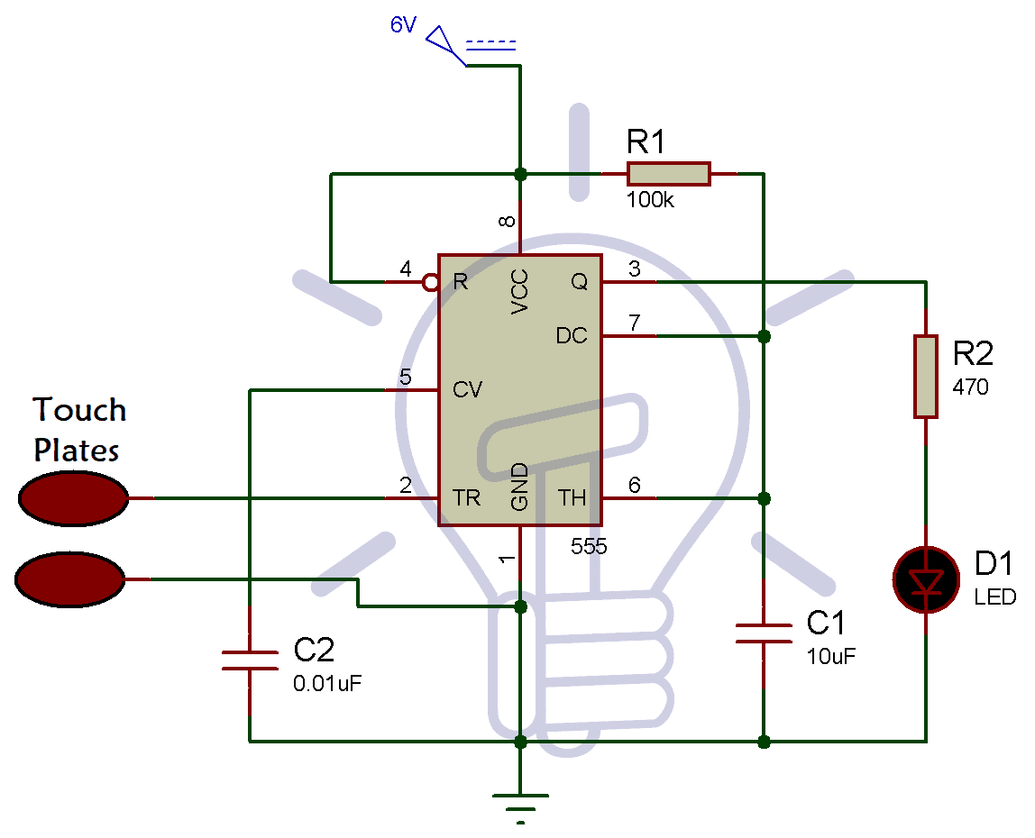
Here, 555 Timer IC is configured in Monostable mode. We can use two pieces of a conductor to make the touch plate, connected with the trigger pin of 555 Timer IC and ground respectively. Pin 5 of 555 timer IC is connected with a capacitor of 0.01 μf. Pin 3 is connected with resistor R2 and Pin 8 is connected with 6V power supply.
- Related Project: Clap Switch Circuit Using IC 555 Timer & BC547 Transistor
Working
Whenever we touch the conductive plates of the touch sensor, the 555 Timer is triggered. The output pin goes high turning ON the LED for some time. You can also connect a buzzer in place of the LED. The pulse duration generated at the output pin entirely depends on the timing resistor and capacitor of the circuit connected at pin 6 and 7 of the 555 Timer IC. That means you can change the duty cycle of the output pulse by changing the value of capacitor C1. The disadvantage of the circuit is that it consumes more power.
- Related Project: Traffic Light Control Electronic Project using IC 4017 & 555 Timer
Simple Touch Sensitive Switch Circuit Using a Transistor
As discussed above, there are a number of ways to design a touch sensitive switch circuit. This touch sensitive switch circuit we are going to discuss now is designed using BC 547 transistor. BC547 is used for amplifying the received input signal. In result, the output obtained has extra sensitivity to the input signal. Take a look at brief discussion of BC 547 Transistor given below.
- Related Project: Water Level Indicator Circuit Diagram- using BC547 Transistor
BC547 Transistor
BC547 is an NPN Transistor which allows a maximum of 100mA to flow across the collector and emitter. It has a gain value of 110 to 800. The gain value determines the amplification capacity of the Transistor. We can’t connect loads that consume more than 100mA using BC 547 Transistor. There are two operating regions of the BC547 transistor. When the Transistor is fully biased then this mode of operation is called saturation region. As soon as the base current is removed, the Transistor becomes fully off and this condition is called cut -off region.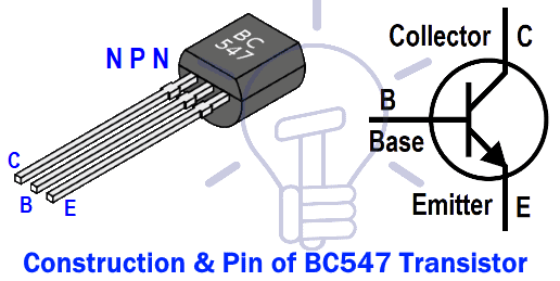
Related Project: Automatic Street Light Control System using LDR & Transistor BC 547
Pinout of BC547
| Pin number | Pin name | Description |
| 1 | Collector | Current flows through the collector |
| 2 | Base | Controls the biasing Transistor |
| 3 | Emitter | Currents drains |
In electronic circuits, BC547 can be used for switching as well as for amplification purpose, we have also described how BC547 behave as a switch or an amplifier.
Switching with BC547:
BC 547 Transistor acts as an open switch during forward bias and will act as a closed switch during reverse bias. Biasing of Transistor can be done by giving the required amount of current to the base pin. Make sure that there biasing current is not greater than 5mA as the current value greater than 5mA will destroy the transistor. To avoid that situation, a resistor is added in series with the base of Transistor. To calculate the resistance at the base pin, use the below formulae.
- Related Electron Project: What is ATMega Microcontrollers & How to Make an LED Project with it?
RB = VBE /IB
Here, VBE = Base-emitter voltage (5V)
IB = current at the base terminal
Amplification Using BC547:
The BC 547 transistor acts as an amplifier when operates in Active region. The DC current gain of the Transistor in this mode can be calculated using the below formulae.
DC current gain = Collector current /Base current
Electrical Characteristics of BC 547:
Collector-Emitter voltage: 65 V
Collector-Base voltage: 80V
Emitter-Base Voltage: 6V
Collector current: 100mA
Storage temperature: 65 to 150 Degree Celsius
Operating temperature: 150 Degree Celsius
Power dissipation: 500 mW
Browse the list of BC 547 Transistor Applications:
- It Can be used in Audio amplifiers, Signal amplifier, etc.
- It can be used in modules like relay driver, LED driver, etc.
Go through the list of components and gather the items to design the touch-sensitive switch circuit using the BC 547 Transistor.
Required Component
- BC547 Transistor
- Resistors
- 6V power supply
- Connectors
- LED
Circuit Diagram of Touch-Sensitive Switch Circuit Using a Transistor

The touch probes are connected with 100 K ohm resistor and base pin of 2nd transistor respectively. Connect the base pin of the 2nd transistor to the emitter pin of the 1st transistor. Here, resistor R1 is the current limiting resistor.
Working
Here, we have used the basic principle of touch-sensitive devices. The skin resistance of the human body is about 600K- 1M. So, whenever the touch conductors sense a touch of the human body, a tiny electric current reach to the base of the transistor through the skin. Therefore, this tiny current triggers the transistor Q1 and current starts conducting from its collector to emitter. As the emitter of Q1 is connected with the base of Q2, Q2 starts conducting and the LED turns ON.
You can even use a single transistor, but the LED will not glow brighter. Therefore, two BC 547 transistors are connected to glow the LED brighter.
Applications
Browse the list of some common applications of touch sensitive switch circuit.
- It can be used in touch-based blinking lights.
- It can be used to detect the electrostatic build up in a room.
- Touch switches for doorbells.
- It can be used to make touch-based buzzers.
Bottom Line
Touch sensitive switch circuits are of great use and are easy to design. In the above discussion, we have designed the circuit using two different components in two different ways. In the first one, we have used 555 Timer IC as the main component and in the second one, we have used the BC 547 transistor as the main component. Both the processes are easy to understand as we have explained the function and role of the main components for the touch-sensitive switch circuit. We hope you have got a good knowledge of both the design process of the circuit and will be able to design this highly reliable touch sensitive switch circuit with ease.
You may also check these simple and easy DIY EE Projects: Electrical and Electronics Projects


It’s very important for us thanks .
Thanks for such helpful information.
I need to improve the circuit with transistors to a blinking led one (the combination of touch sensor and blinking led using transistors)
Could you please guide me how can I do that?