Electronic Eye Circuit – Using LDR and IC 4049 For Security Control
Electronic Eye Circuit for Security Control System
In this era of electronics, we always come across several electronic devices and machines that are working superbly to ease our workflow to a great extent. No doubt, electronic devices are saving a lot of manpower and un-necessary effort. In this article, we will be discussing the “Electronic eye” circuit that is popularly known as magic eye. This circuit can be used in devices to detect the presence of light automatically and operate the circuit accordingly. We have also described the features of main components used in the circuit to make you understand the working of electronic eye more clearly.
- Related Post: What is a Bionic Eye and How Does it Work?

Electronic eye circuit uses a photodetector for detecting the presence of a light. Then according to the intensity of light this device turns ON the light when it becomes dark and vice versa.
Since the device is capable of working automatically, this eliminates the need of manual switching of the device and hence saves the manpower. In our electronic eye circuit, we have used light dependent resistor (LDR) to detect the presence of light that falls on the circuit.
Before starting with the design process of electronic eye circuit, let us discuss the working and function of two main components of the circuit i.e. LDR and IC 4049 (NOT Gate Buffer).
- Related Project: Automatic LED Emergency Light Circuit using LDR
Light Dependent Resistor (LDR)
LDRs is used to indicate the presence or absence of light. If the intensity of light is very low (dark), the resistance of LDR is very high. As soon as the LDR is exposed to light, the resistance drops largely depending on the intensity of light. However, the resistance of LDR is inversely proportional to the intensity of light. So, higher the intensity of light larger will be the voltage drop. Based on the material, LDR is of two types namely intrinsic and extrinsic photoresistor.
Characteristics of LDR
Wavelength: LDR is not sensitive in a certain wavelength range. The sensitivity of a photoresistor varies with the light wavelength. Extrinsic LDR are generally designed for longer wavelength of a light
Sensitivity: LDR has lower sensitivity than photoconductors and photodiodes. Even if the sensitivity of the light is kept constant, the resistance of the device may still vary due to the change in temperature. This is the reason LDRs are not suitable for precise light intensity measurement.
Latency: In LDRs, there is time latency between changes in illumination and changes in resistance. This phenomenon is called resistance recovery rate. It usually takes some time for the resistance to drop completely when light is applied after total darkness. It takes around 10 ms for the resistance of LDR to drop completely and up to 1 second for the resistance to rise back to the previous value, after removal of the light.
Construction of light dependent resistor: To manufacture a cadmium sulfide LDR, highly purified cadmium sulfide powder and inert binding materials are used. The disc of the LDR is mounted in a glass envelope to prevent surface contamination.
- Related Project: Automatic Night Lamp Using Arduino and LDR
Applications of LDR
- Light-dependent resistors are mainly used in line following robots that used LDR to determine the change of course.
- LDRs are used in photography light meters
- Light-dependent resistors are generally used in night lights
- Outside the sensing applications, LDRs are also used in audio compressors
Now, you have got a good knowledge of using LDR in the electronic eye. The second main component used in the circuit is IC 4049. Let us discuss the IC and its working in brief.
- Related Project: Automatic Street Light Control System using LDR
IC 4049 (Hex Inverter Buffer)
IC 4049, also known as hex inverter buffer IC, is used for the conversion of high logic level to low. 4049 IC can handle two TTL loads as it has higher input supply voltage with a current rating of 1mA. The main application of IC 4049 is creating voltage multiplier circuit. It can also be used for square wave oscillator.
This hex buffer IC converts low logic level to high and vice versa. You can design many hobbyist projects like simple LED torch light, street lights automation and water level indicator.
Pinouts
Go through the below table to understand the pinouts of IC 4049 and its working:
| Pin Number | Pin Name | Input /Output |
| 1 | VDD | – |
| 2 | Ground | OUTPUT |
| 3 | A | INPUT |
| 4 | H | OUTPUT |
| 5 | B | INPUT |
| 6 | I | OUTPUT |
| 7 | C | INPUT |
| 8 | VSS | – |
| 9 | D | INPUT |
| 10 | J | OUTPUT |
| 11 | E | INPUT |
| 12 | K | OUTPUT |
| 13 | NC | – |
| 14 | F | INPUT |
| 15 | L | OUTPUT |
| 16 | NC | – |
Technical Specifications of IC 4049
- Input voltage range: 3v-18v
- Supply current – 50 mA
- Input capacitance -22.5 pf
Related Post: Cable and Wire Tester Circuit Diagram
Applications of hex inverter IC 4049
- It can be used in voltage multiplier circuit
- High to low logic converters
- It can be used in CMOS hex buffer
- As a source driver
Now, you are well-aware with the working of both the components i.e. IC 4049 and LDR. Now we will start the design process of electronic eye using some easily available electronic components. Gather the below components and start designing the circuit of electronic eye.
Related Project: Traffic Light Control Electronic Project using IC 4017 & 555 Timer
Components Required
- IC 4049
- Light dependent resistor (LDR)
- 220 K ohm resistor
- LED
- Buzzer
- Battery – 9V
- Switch
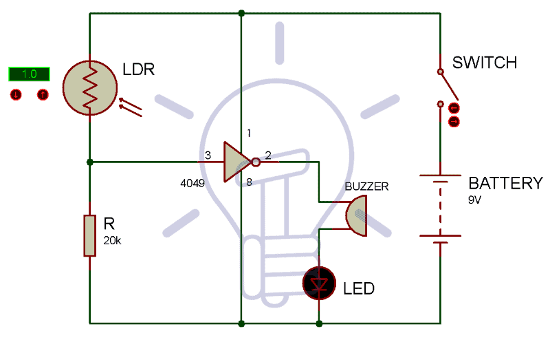
Electronic Eye Circuit Diagram
Assemble the component as shown in the circuit diagram given below. Connect the LDR with IC 4049. Connect the buzzer and IC 4049 as shown in the below. Pin 1 of the 4049 IC is connected to the power supply and Pin 8 is grounded.
Working Of Electronic Eye Circuit
The Output has two stages mainly High and Low and can’t be in any other intermediate stage. The circuit is powered by 9v battery to make it portable. However, IC 4049 consists of six independent NOT gates but we have only used one NOT gate in this circuit design.
We have made a potential divider circuit using LDR and 220 k ohm resistor connected in series. Since voltage is directly proportional to the conductance, more voltages will be produced at the output of the divider circuit when LDR is exposed to light and vice versa.
Then that output voltage of the divider is fed to the input of NOT gate of Hex inverter 4049 IC. Therefore, when the intensity of light is low over the LDR (which means dark), the output of the divider will be low. In result, Pin 2 of NOT gate IC gets high and LED connected to the output gets activated. In simple words, whenever LDR is exposed to the light beam, the resistance of LDR increases and this makes the Hex inverter IC 4049 produce a sound in the buzzer.
- Related Project: Clap Switch Circuit Electronic Project Using 555 Timer
Applications of Electronic Eye
Electronic eye is generally a photoresistor that turns ON the light when it becomes dark. You can use the electronic eye to in the place where you need to operate a device when there is dark and no light is present and switch OFF automatically once the light beam strikes the surface of the LDR. This feature can be very useful in variety of application in daily life:
- It can be used as automatic guest indicator at the door in offices, schools, colleges and apartments.
- It can be used in security-controlled systems.
- This can be used in highway as vehicle counter, to count the number of vehicles
- It can be used in automatic wrapping machine in industries and factories to wrap materials that are manufactured
- It can be used in cameras to automatically determine the proper aperture and posture
Bottom Line
Electronic eye circuit is of great use and can be assembled using cost-effective electronic components. We have used some simple electronic components to design the circuit. We have used two main components namely LDR and hex inverter IC 4049 in our project. The working and function of both the components are well-described in the article to make you understand the working of both the components in the Electronic eye circuit project. We hope you will be able to design the “electronic eye” circuit on your own using the information provided in the above discussion.
Related Projects:


Awesome project. I have tested this magic eye circuit (also known as electronic eye) …