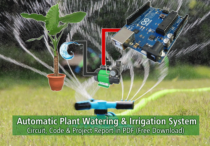
Automatic Plant Watering & Irrigation System – Circuit, Code & Project Report
Automatic Plant Watering System – Full Source Code, Circuit & Project Report – PDF Download
Introduction
In daily operation related to watering the plants are the most important cultural practice and the most labor-intensive task. No matter whichever weather it is, either too hot and cold or too dry and wet it is very crucial to control the amount of water reaches to the plants. So, It will be effective to use an idea of automatic plant watering system which waters plants when they need it. An important aspect of this project is that: “when and how much to water”. To reduce manual activities for the human to watering plant, an idea of plant watering system is adopted. The method employed to monitor the soil moisture level continuously and to decide whether watering is needed or not, and how much water is needed in plant’s soil. This project can be grouped into subsystems such as; power supply, relays, solenoid valve, Arduino GSM shield, Soil moisture sensor and LCD.
Essentially, system is design and programmed in such way that soil moisture sensor senses the moisture level of plants at particular instance of time, if moisture level of sensor is less than the specified value of threshold which is predefined according to the particular plant’s water need then the desired amount of water is supplied till it reaches to the predefined threshold value.
System reports its current states and sends the reminder message about watering plants and to add water to the tank. All this notification can be done by using Arduino GSM shield.
- Related Project: Rain Alarm Circuit – Snow, Water and Rain Detector Project
Aim of the project:
Since nowadays, in the age of advanced technology and electronics, the life style of the human should me smart, simpler, easier and much more convenient. So, therefore; there is a need for many automated systems in human’s daily life routine to reduce their daily activities and jobs. Here an idea of one such system named as automatic plant watering system is very useful. As many people are facing a lot of problem watering the plants in the garden, especially when they away from the home. This model uses sensor technologies with microcontroller in order to make a smart switching device to help millions of people.
In its most basic form, system is programmed in such a way that soil moisture sensor which senses the moisture level from the plant at particular instance of time, if moisture level of the sensor is less than the specified value of threshold which is predefined according to the particular plant than the desired amount of water is supplied to plant till it’s moisture level reaches to the predefined threshold value. System involves humidity and temperature sensor which keep tracks the current atmosphere of the system and has an influence when watering happens. Solenoid valve will control the water flow in the system, when Arduino reads value from moisture sensor it triggers the solenoid valve according to the desired condition. In addition, system reports its current states and sends the reminder message about watering plants and gets SMS from the recipient. All this notification can be done by using Arduino GSM shield.
- Related Project: Water Level Indicator Circuit Diagram- Two Simple Projects
Background of the System
It has been studied in the school from the science’s books that the plants are very imperative for all the humanity in many aspects. As they keep the environmental clean by producing fresh oxygen time to time. Automatic plant watering system have been seen becoming much more with the rise in the everyday objects being connected to the advanced technologies, these systems are implemented at a growing rate. Places like homes as well as on industrial levels. The main use of these systems is efficiency and easy to use.
Plant watering system provides the ability to plant lovers to take of their home plant while they are away – through the use of efficient and reliable components such as different types of sensor technologies.
There are several different/uncomplicated types of indoor plant watering system, depending on the level of automation needed.
- Related Project: Smart Irrigation System – Circuit Diagram and Code
In the final pdf report (free downloadable link is given at the end of the post content), the following sections are described in details.
- Plant Watering Globes and Spike
- Indoor Drip Watering System
- Sensor Technology
- Temperature and Humidity Sensors
- Temperature Sensor
- Humidity Sensors
- Soil Moisture Sensors
- Bi-Metallic Thermostat
- Thermistor
- Resistive Temperature Detectors (RTD)
- Thermocouples
- Sensor ICs, LM35
- Digital Temperature Sensor (ADT7301)
- DHT11 and DHT22
- GSM Module
- GSM Architecture
- Relay
- Transistor
- Hitachi 16×2 LCD
Related Project: What is ATMega Microcontrollers & How to Make an LED Project with it?
Products & Components Specifications
| Requirement ID | SRS-GSM-001 |
| Title | GSM Module |
| Description | System includes the GSM module, which sends alert SMS to the recipient and receive a SMS from the user. |
| Version | Version 1.0 |
| Requirement ID | SRS-Microcontroller -001 |
| Title | ATmega328p |
| Description | System includes the microcontroller which usually comes with Arduino Uno. this microcontroller reads the reading from the sensor and controls the overall system. |
| Version | Version 1.0 |
| Requirement ID | SRS-Temperature and Humidity-001 |
| Title | DHT11 |
| Description | System includes the temperature and humidity sensor, which keeps track of the current temperature and humidity values from the surrounding and sends the reading back to microcontroller. |
| Version | Version 1.0 |
| Requirement ID | SRS-Moisture-001 |
| Title | Grove Soil Moisture Sensor |
| Description | System includes the soil moisture sensor, which takes the reading from the moisture of the soil and sends the reading back to microcontroller. |
| Version | Version 1.0 |
| Requirement ID | SRS-LCD-001 |
| Title | Hitachi 16×2 LCD |
| Description | System includes the LCD interface for the user, which displays the reading taken by the different types of sensors in the system. |
| Version | Version 1.0 |
Arduino Based Automated Plant Watering System:
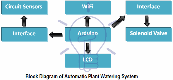
Automatic Plant Watering Block Diagram

Schematic Circuit Diagram of Automatic Plant Watering & Irrigation System
According to this system there are two functional components in this project i.e. Moisture sensor and motor/water pump. In its most basic form moisture sensor senses level of the soil moisture. Then motor/water pump supplies water to plants.
Click image to enlarge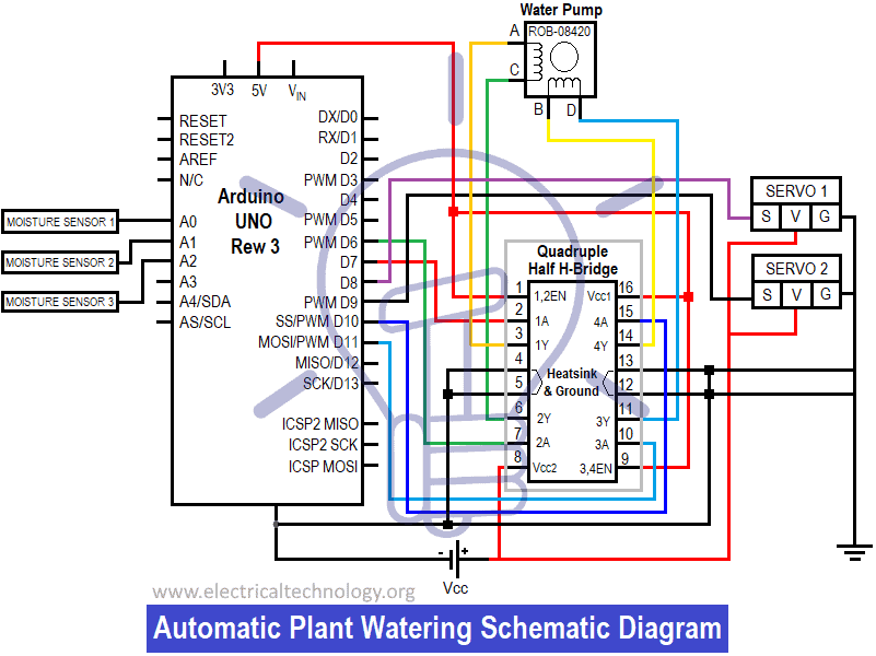
Schematic above in above figure describes the overall behaviour of the system. Project uses Arduino Uno to controls the motor. It consists of H-bridge which controls the flow of servo motor i.e. clock or anti clock direction. Moisture sensor measures the level of soil and sends the signal to Arduino then Arduino will open the servo motor if watering is required. Then the motor/water pump supplies water to the plants until the desired moisture level is reached.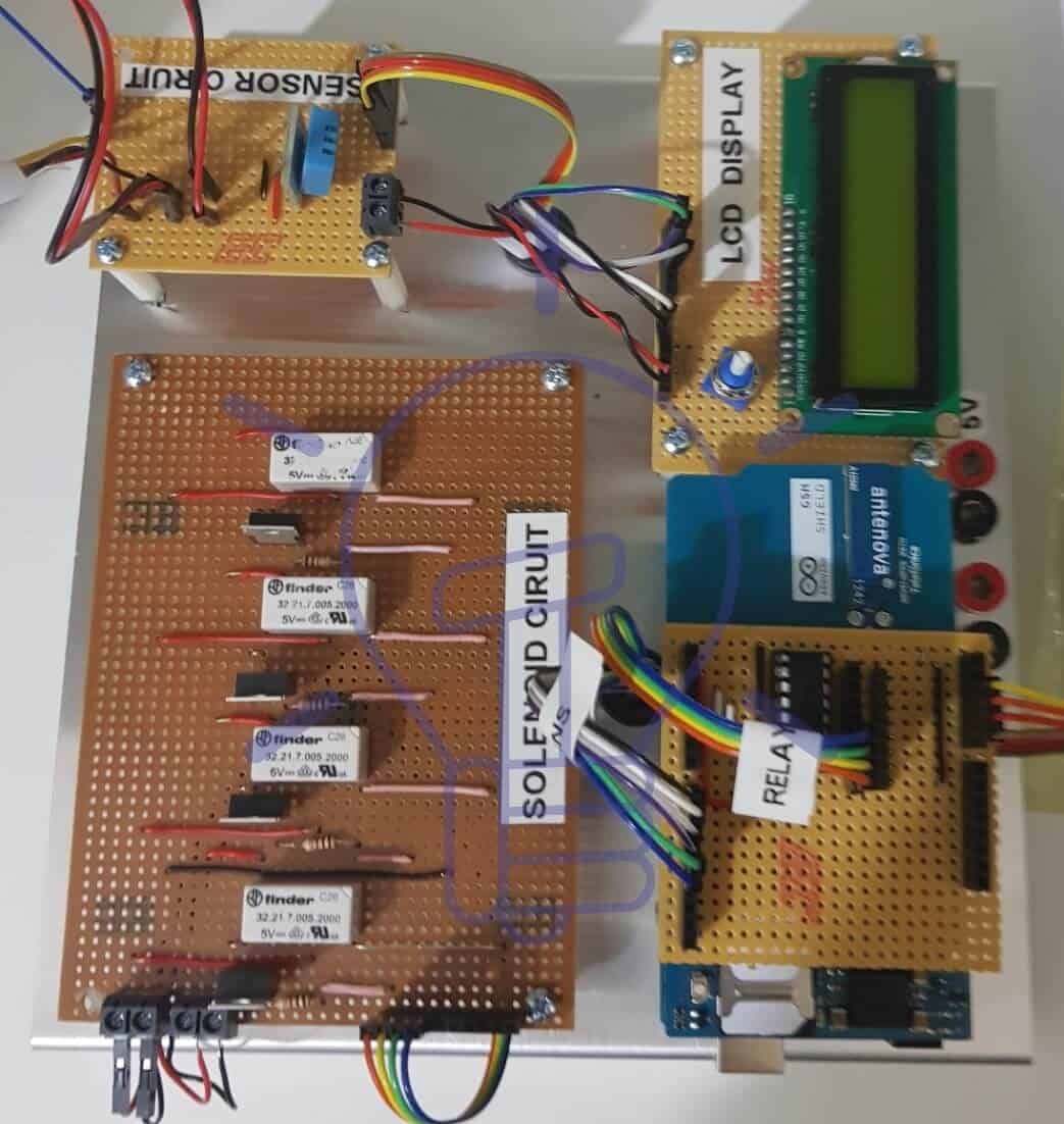
Form the prototype in above figure moisture sensor senses the moisture level and sends the signal to Arduino and then Arduino opens water pump with the help of H-bridge and waters the particular plant. This is done by using Arduino IDE software.
Related Project: Traffic Light Control Electronic Project using IC 4017 & 555 Timer
Project Design
This section is talk about any work finished in software design and hardware design. It also goes into insight about what the system includes and why different components were chosen to make a fully completed Automated Plant watering system. Consider a diagram in figure shows the basic conceptual model of the system using chosen components.
The functionality of block diagram shown in above figure of the automated plant watering system is illustrated below:
- The system includes GSM module which sends SMS to the recipient and receives SMS from the recipient.
- It uses soil moisture, temperature and humidity sensors.
- It also includes solenoid valves along with solenoid circuit which controls the flow of water through the solenoid valves.
- The moisture sensor is used to determine the moisture level of the particular plant. This moisture level is read by the microcontroller, as it loops around and sees if the value from the sensor is above the threshold value or not. If the value is above the predefine value than GSM module is ready to send a SMS to the recipient.
- The temperature and humidity sensor is used to determine whether it is too hot for the plant or the humidity is too high to handle. This is read by the ATmega328p (Read more about What is ATmega) chip on Arduino Uno. these reading will be used to determine if all the solenoid in the system should be On or Off.
More components details can be found in the pdf file (below)
Related Project: What is Raspberry Pi? Creating Projects using Raspberry Pi
Hardware Design
Sensor Schematic
Figure below shows the schematic of the Sensor circuit. As all the sensor connected with the Arduino analogue pin A0-A3. Pin A0 was reserved for the temperature and humidity sensor whereas pins A1-A3 were reserved for moisture sensors. All the sensors have common power 5V and Ground as shown in the schematic.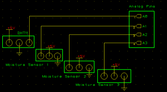
LCD Schematic:
Figure below shows the schematic of the LCD. Digital pin 8 – 13 was reserved for the LCD as shown in the Schematic. Pin 1 and Pin 3 are the power and ground whereas pin 2 is the contrast pin on the LCD which controls the contrast and connected with the potentiometer. It must be kept in mind while connecting LCD is that digital pins from Arduino and data pins from LCD has to be connected in correct order otherwise LCD will display only garbage on the screen.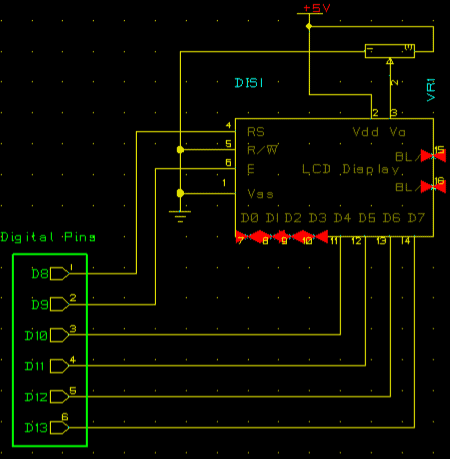
Solenoid Schematic
Diagram underneath in figure below shows the circuit diagram of the solenoid circuit. Digital pin 4 – 7 was reserved for the Solenoids. As the circuit consists of relays, transistors, resistors, and LEDs instead of the solenoid (CadStar doesn’t have Solenoid symbol). In the schematic relays utilizes 5V. Whereas 5V also goes into NO channel of the relays as well this is because in the schematic LEDs replaces solenoid which works on (5V) followed by 220-ohm resistor.
- Related Project: Voice Recognition Based Home Automation System
So, when the voltage is applied to the base of the transistors. Transistor switches to ground allowing the coil of the relay to get magnetized and switches itself to Normally closed channel, due to which LED connected to that particular relay comes On and when the voltage applied on the transistor base is drops, transistor switches itself back to normal and the coil of the relay get de-magnetized and relay switches to NO channel again, due to which LED goes Off again.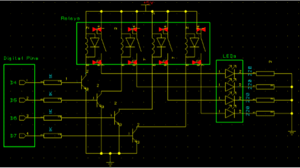
After finishing off all the Schematic of the circuit, next step is to build them on the Veroboard. It is important to design the circuit on stripboard layout planning sheet in advance because there are certain principles for designing a circuit on Veroboard which is as follows:
- Mark out the Vs and GND power line first on the top right of the stripboard layout planning sheet.
- Remember to cut the track between the pins of an IC. Mark the cuts on the diagram with an X.
- Try to make resistor and axial capacitors lay flat on the stripboard. Resistors usually require a gap of 4 holes, capacitor a gap of 8 holes.
- If possible numbers the pin of the ICs.The bottom side of the Veroboard consist of the copper tracks in which voltage flows works horizontally. Different Veroboard design of the schematics above are shown below:
Related Project: Fully Automatic Water Level Controller using SRF04
Software Design
After getting the hardware done, it’s time to test the hardware with the software. In this section, the implementation of the software design will be described in detail for each of the different automation/ technologies used within the system. This includes the Arduino code written and uploaded to the Arduino.
The first thing done was to get the solenoid circuit working and how the solenoid would act from the microcontroller perspective. For this, a small flow chart was done which can be seen under software flow section in figure above.
Arduino IDE was used to get the upload the software on the Arduino. For the basic solenoid circuit, a simple program was written which basically blinks the LED every 1 sec. digital pin 4, 5, 6 and 7 was defined initially which test the program and the circuit. So, when the program runs it makes all basic initializations, defines all the output pins in void setup () and then jumps into the void loop () where it constantly runs and blinks LEDs on every 1sec.
After that, a small program was written and uploaded to the Arduino which gets the readings from the different sensor and prints them on the LCD. For this, a small flow chart was done which can also be seen under software flow section in the given figure. When the program goes into the void loop () it gets the readings from the sensor and does all the basic calculation and prints them on LCD.
Related Basic Electronics Project: Automatic Street Light Control System using LDR & BC 547 Transistor
Next thing is to upload the software for GSM module to the Arduino, through which GSM could communicate with the microcontroller. Modem test was done initially which does all the basic initialization and libraries for the GSM and gets the IMEI number and see if the modem is functioning properly once start communicating with Arduino. The next step is network connection test which basically initialized the GSM and displays all the other network which GSM module can support.
Once the GSM module is tested and functioning properly it’s time to use GSM module to communicate with the recipient, which means sends SMS to the recipient and receive SMS from them. In order to do that, another simple Arduino wiring program was written and uploaded to the Arduino. The program initialized the GSM and send SMS to the recipient in contrast another Arduino program was written in which GSM receive the SMS from the end user.
Finally, once all the software design was done it’s time to merge all the software design together and build a final working software for the system. Different algorithm approaches were applied which can be seen under software flow section to get the final software working and does it what it supposed to do. The above figure shows the working of the final software where it takes a reading, send SMS, receive SMS and start doing what it was doing previously.
Note: All the software code can be seen in the appendix below.
NOTE: all the software code can be viewed in the appendix. The output from the modem test and network connection test was not included in the report because the actual report was done after the submission of hardware.
Related Project: How to make basic Electrical & Electronics Projects in LabVIEW?
Project Construction and Software Testing
After getting all the hardware and software design done successfully it’s time for the project construction and testing. In this section of the report, details will be given on how the different hardware design gets implemented and tested. This section also talks about if there was any hidden problem within the software code that was important to troubleshoot and evacuate and to build the project successfully. the step by step process can be seen in the full project report in pdf file given below such as construction and testing procedure.
Software Testing
Software testing phase is also an important aspect of the project development. Software testing is a procedure of executing a program or application with the goal of finding the software bugs. It can likewise be expressed as the process of validating and verifying that a software program or application meet its technical requirement, works as accepted and can be executed with a similar trademark. To do the software testing different approaches were adopted. A software requirement specification (SRS) document was written which fully addressed the expected behavior of a software system.
Related Project: Clap Switch Circuit Electronic Project Using 555 Timer
| Requirement ID | SRS- Sensor -010 |
| Title | Sensor |
| Description | Sensors in the system take the readings and send it back to the microcontroller. |
| Version | V 1.0 |
| Requirement ID | SRS- Data -020 |
| Title | Data Display |
| Description | When the users try to get the reading from the system. Display should have displayed data to user for example: temperature and humidity value followed by moisture readings. |
| Version | V1.0 |
| Requirement ID | SRS- Microcontroller -030 |
| Title | Microcontroller |
| Description | Microcontroller in the system act as a brain of the system which manages everything in the system |
| Version | V1.0 |
| Requirement ID | SRS- Latch -040 |
| Title | Latch |
| Description | Latch in the system expands the digital pins for the microcontroller |
| Version | V1.0 |
| Requirement ID | SRS- GSM-050 |
| Title | GSM |
| Description | System will react by sending a SMS alert to the recipient whenever microcontroller tells it to do so. |
| Version | V1.0 |
After writing the SRS document software design moved in to static testing phase which includes reviewing of the document. This is where verification of the requirements occurs. There are four diverse types of verification methods defined below:
- Inspection (I): control or visual verification
- Analysis (A): verification based on analytical evidences
- Demonstration (D): verification of operational characteristics, without quantitative measurement.
- Test (T): verification of quantitative characteristics with quantitative measurement. For each requirement of the SRS document, a verification method is defined with abbreviation of I, A, D and T.
Verification:
| Requirement ID | Requirement Title | Method |
| REQ-010 | Verify that the sensors of the system get readings | I |
| REQ-020 | Verify that the Data is Displayed on the screen. | D |
| REQ-030 | It is verified that the microcontroller of the system is managing or working properly as it gives 100% result for every request. | D |
| REQ-040 | Verify that latch circuit was doing what is supposed to do. That take sin 3 input and spits out 8 pins | A |
| REQ-050 | Verify that the SMS has been sent and received by GSM | D |
Results
As all the testing done with satisfactory result. Since there is no as such particular result that has to be documented. As the system works with moisture and DHT11 (temperature and humidity) sensor which takes reading according to the current room temperature and humidity. Readings from the moisture sensor in the circuit also depend on what the current moisture level is for the plant. Otherwise, overall result coming out from the circuit in terms of functionality was good for motivation.
Related Post: Arduino PWM Programming and its functions in Arduino
Final and full software code for Automatic Watering plants & irrigation systems
Note: More Codes related to the project can be find in the pdf file such as sample Code to test Solenoid Valve, Code for testing System Sensors, GSM Modem Test Code, GSM Network Connection Code, GSM sends SMS alert Code, GSM Receive SMS code,
Final Auto Watering Plants Project Code
#include <dht.h>
#define dht_dpin A0
dht DHT;
//———————–
#include <LiquidCrystal.h>
LiquidCrystal lcd (8, 9, 10, 11, 12, 13);
//———————————-
int plantPotMoisture[3] = {A1, A2, A3};
//———————
#include <GSM.h>
#define PINNUMBER “”
GSM gsmAccess; // include a ‘true’ parameter for debug enabled
GSM_SMS sms;
char remoteNumber[] = “0899506304”;
String moistureMessage = “Moisture is Low on sensor: “;
String SMS_Alert = “Sending SMS!”;
String humidityMsg = “Humidity is High. Open All Solenoids”;
String tempMsg = “Temperature is too HIGH!..Open ALl Solenoids “;
String messageBuffer = “”;
char senderNumber[20];
String stringOne = “Opens1”;
String stringTwo = “Opens2”;
String stringThree = “Opens3”;
String stringFour = “OpenAll”;
//—————
#define solenoidData 5
#define solenoidClockster 4
#define solenoidLatch 6
//—————
const int master = 0;
const int slave1 = 1;
const int slave2 = 2;
const int slave3 = 3;
boolean takeReadings = true;
int serialSolenoidOutput = 0;
void setup()
{
pinMode(solenoidData, OUTPUT);
pinMode(solenoidClockster, OUTPUT);
pinMode(solenoidLatch, OUTPUT);
digitalWrite(solenoidLatch, HIGH);
digitalWrite(solenoidLatch, LOW);
shiftOut(solenoidData, solenoidClockster, MSBFIRST, 0);
digitalWrite(solenoidLatch, HIGH);
//————————-
Serial.begin(9600);
lcd.begin (16, 2);
lcd.clear();
lcd.setCursor(0, 0);
lcd.print(“Wait Until”);
lcd.setCursor(0, 1);
lcd.print(“GSM Initialized!”);
boolean notConnected = true;
while (notConnected)
{
if (gsmAccess.begin(PINNUMBER) == GSM_READY)
notConnected = false;
else
{
Serial.println(“Not connected”);
delay(1000);
}
}
}
void loop()
{
if (takeReadings)
{
moistureSensor();
TempAndHumidity ();
if (DHT.humidity > 50 || DHT.temperature > 25 && takeReadings )
{
takeReadings = false;
if (DHT.humidity > 50)
{
sendSMS(humidityMsg);
}
else if (DHT.temperature > 25)
{
sendSMS(tempMsg);
}
while (!takeReadings)
recieveSMS();
}
if (plantPotMoisture[0] > 30 || plantPotMoisture[1] > 30 || plantPotMoisture[2] > 30 && takeReadings)
{
takeReadings = false;
if (plantPotMoisture[0] > 30)
{
sendSMS(moistureMessage + “1”);
}
else if (plantPotMoisture[1] > 30)
{
sendSMS(moistureMessage + “2”);
}
else
{
sendSMS(moistureMessage + “3”);
}
while (!takeReadings)
recieveSMS();
}
}
}
void moistureSensor()
{
for (int i = 0 ; i < 3; i++)
{
lcd.clear();
plantPotMoisture[i] = analogRead(i);
plantPotMoisture[i] = map(plantPotMoisture[i], 550, 0, 0, 100);
Serial.print(“Mositure” + i );
lcd.print(“Mositure” + i);
Serial.print(plantPotMoisture[i]);
lcd.print(plantPotMoisture[i]);
Serial.println(“%”);
lcd.print(“%”);
delay(1000);
}
}
void TempAndHumidity ()
{
DHT.read11(dht_dpin);
lcd.setCursor(0, 0);
lcd.print(“Humidity=”);
Serial.print(“Current humidity = “);
Serial.print(DHT.humidity);
lcd.print(DHT.humidity);
lcd.print(“%”);
Serial.print(“%”);
Serial.print(“temperature = “);
Serial.print(DHT.temperature);
Serial.println(“C”);
lcd.setCursor(0, 1);
lcd.print(“temp=”);
lcd.print(DHT.temperature);
lcd.print(“C “);
delay(1000);
lcd.clear();
}
void sendSMS(String messageToSend)
{
Serial.print(“Sending a message to mobile number: “);
Serial.println(remoteNumber);
Serial.println(“SENDING”);
lcd.print(SMS_Alert);
Serial.println();
Serial.println(“Message:”);
Serial.println(messageToSend);
sms.beginSMS(remoteNumber);
sms.print(messageToSend);
sms.endSMS();
Serial.println(“\nCOMPLETE!\n”);
lcd.clear();
lcd.print(“Completed!!!”);
}
void recieveSMS()
{
char c;
if (sms.available())
{
lcd.clear();
lcd.print(“Message received from:”);
delay(800);
lcd.clear();
sms.remoteNumber(senderNumber, 20);
lcd.print(senderNumber);
while (c = sms.read())
{
Serial.println(c);
messageBuffer += c;
}
Serial.println(messageBuffer);
if (messageBuffer == stringOne)
{
toggleSolenoid1();
takeReadings = true;
}
else if (messageBuffer == stringTwo)
{
toggleSolenoid2();
takeReadings = true;
}
else if (messageBuffer == stringThree)
{
toggleSolenoid3();
takeReadings = true;
}
else if (messageBuffer == stringFour)
{
toggleAll();
takeReadings = true;
}
else
{
takeReadings = true;
}
messageBuffer = “”;
Serial.println(“\nEND OF MESSAGE”);
// Delete message from modem memory
sms.flush();
Serial.println(“MESSAGE DELETED”);
}
delay(1000);
}
void toggleSolenoid1()
{
solenoidWrite(master, HIGH);
delay(1000);
solenoidWrite(slave1, HIGH);
delay(1000);
solenoidWrite(slave1, LOW);
delay(1000);
solenoidWrite(master, LOW);
delay(1000);
}
void toggleSolenoid2()
{
solenoidWrite(master, HIGH);
delay(1000);
solenoidWrite(slave2, HIGH);
delay(1000);
solenoidWrite(slave2, LOW);
delay(1000);
solenoidWrite(master, LOW);
delay(1000);
}
void toggleSolenoid3()
{
solenoidWrite(master, HIGH);
delay(1000);
solenoidWrite(slave3, HIGH);
delay(1000);
solenoidWrite(slave3, LOW);
delay(1000);
solenoidWrite(master, LOW);
delay(1000);
}
void toggleAll()
{
solenoidWrite(master, HIGH);
delay(1000);
solenoidWrite(slave1, HIGH);
delay(1000);
solenoidWrite(slave2, HIGH);
delay(1000);
solenoidWrite(slave3, HIGH);
delay(1000);
solenoidWrite(slave1, LOW);
delay(1000);
solenoidWrite(slave2, LOW);
delay(1000);
solenoidWrite(slave3, LOW);
delay(1000);
solenoidWrite(master, LOW);
delay(1000);
}
void solenoidWrite(int pin, bool state)
{
if ( pin >= 0 && pin < 8)
{
if (state)
serialSolenoidOutput |= (1 << pin);
else
serialSolenoidOutput &= ~(1 << pin);
}
digitalWrite(solenoidLatch, LOW);
shiftOut(solenoidData, solenoidClockster, MSBFIRST, serialSolenoidOutput);
digitalWrite(solenoidLatch, HIGH);
}
Full Project Report Automatic Watering Plants System (PDF) Free Download
Related Posts:


VIDEO LEACTURE ON THIS PROJECT
kindly contact me on ramiharraz@gmail.com
what can be done to improve this system?