Difference Between Full Load Amperes (FLA) and Full Load Current (FLC)
When working with electric motors and related equipment, professionals often encounter the terms FLA and FLC. Though sometimes used interchangeably, these terms represent different concepts and serve distinct purposes in electrical design, motor protection, and equipment sizing.
While Full-Load Amperes (FLA) and Full-Load Current (FLC) are closely related, it’s important to understand what they mean, where each is used, and how they differ.
Motor circuit design, calculations, and protection differ significantly from other types of circuits, especially in how they handle overcurrent conditions. This is because an electric motor typically draws 6 to 8 times more current during startup than it does during normal operation. This surge is known as inrush current, a temporary overload condition that requires properly selected overcurrent protective devices to ensure the motor operates smoothly and safely.
Overcurrent protection for motors is divided into two main categories:
- 1. Short-Circuit and Ground-Fault Protection:
Fuses and circuit breakers are used to protect the motor’s branch-circuit conductors and wiring from short circuits and ground faults. The protective devices must be sized to handle the inrush current without tripping unnecessarily, yet not so oversized that they fail to protect the circuit from actual fault conditions.
- 2. Overload Protection:
Thermal overload relays are used to protect the motor and associated wiring from sustained overloads during normal operation. These devices are designed to withstand the high inrush current temporarily during startup, allowing the motor to start without interruption while still protecting against prolonged overloads.
So, which current value should you use when selecting protective devices for short-circuit and ground-fault protection or for overload protection, FLA or FLC?
Choosing the wrong value can result in insufficient protection, potentially damaging the motor and associated equipment. Therefore, it’s essential to understand the correct application of both FLA and FLC in motor protection scenarios.
What is FLA?
FLA stands for Full Load Amperes. It refers to the actual current or rated current in amperes drawn by an electric motor when operating at rated voltage, rated frequency, and delivering full-rated horsepower. This value is typically printed on the motor’s nameplate by the manufacturer.
In the National Electrical Code (NEC), the value of Full Load Amperes (FLA) is referred to as the “Nameplate Value” as defined in NEC 430.6(A)(2).
In the International Electrotechnical Commission (IEC) standards, the rated current is represented by “Ib“, while the Full Load Amperes (FLA) is denoted as “IN“, according to IEC 60364.
Where to Use FLA?
The value of FLA is primarily used to determine the motor overload protection settings (e.g., thermal overload relays). It may also be used to determine the conductor ampacity for non-continuous duty motors (430.22(E) and sizing overcurrent devices for branch-circuit short-circuit and ground-fault protection.
The use of Full-Load Amperes (FLA) is must be applied to motors operating below 1,200 RPM, multispeed motors (where the Full-Load Current (FLC) varies with speed), and high-torque motors having high FLCs values.
If the overload protection is separated from the short-circuit protection, the rating of overload protection should be 115% of the FLA.
How to Use FLA?
430.32(A)(1) states that the rating of overload protective device (such as relay) must be rated based on the motor nameplate full-load amperes (FLA) and must not exceed:
- 125% for motors with a service factor 1.15 or greater
- 125% for motors with a marked temperature rise 40°C or less
- 115% for all other motors
If the overload protection provided by 430.32(A)(1) and 430.32(B)(1) is unable to start the motor, higher overload device ratings can be used as per 430.32(C)(1) as follow while it should not exceed the motor’s FLA:
- 140% for motors with a service factor ≥ 1.15
- 140% for motors with temperature rise ≤ 40°C
- 130% for all other motors
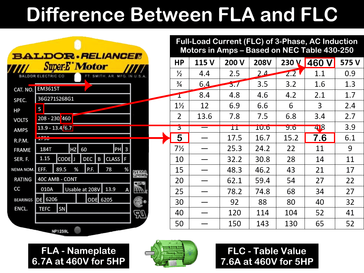
The value of Full Load Ampere (FLA) is shown in the following motor’s nameplate S.No 4. It clearly shows a 3-phase 5 HP induction motor will take 6.7A at 460V. Keep in mind that the value of Full load current (FLC) in ampere for the same motor is 7.6A in NEC table 430.250 (Table given below in the FLC section).

Warning: Overload protective devices sized based on FLA do not provide protection against short circuits or ground faults in the branch circuit. They only protect against excessive current caused by overload conditions.
What is FLC?
FLC stands for Full Load Current. It is the standardized value of current drawn by a motor of a given horsepower, voltage, and type, based on tables in the National Electrical Code (NEC) and UL 508A. FLC is not measured, but rather assumed for design and calculation purposes.
In the National Electrical Code (NEC), the value of Full Load Current (FLC) is referred to as the “Table Value” as defined in NEC 430.6(A)(1).
The values of Full-Load Current (FLC) are mentioned in the National Electrical Code (NEC) tables as follow:
- Table 430.247 for DC motors
- Table 430.248 for Single-phase AC motors
- Table 430.248 for Induction type (Squirrel Cage / Wound Rotor) motors
- Table 430.250 for Three-phase AC motors
Similarly, values of FLCs are published in 508A standard as:
- Table 50.1 for AC motors
- Table 50.2 for DC motors
For example, the following table based on NEC Table 430-250 shows the values of Full-Load Current (FLC) in amperes for 3-Phase. AC induction motors (squirrel-cage and wound rotor).
| Full-Load Current (FLC) of 3-Phase. AC Induction Motors in Amps – Based on NEC Table 430-250 | ||||||
| HP | 115 V | 200 V | 208V | 230 V | 460 V | 575 V |
| ½ | 4.4 | 2.5 | 2.4 | 2.2 | 1.1 | 0.9 |
| ¾ | 6.4 | 3.7 | 3.5 | 3.2 | 1.6 | 1.3 |
| 1 | 8.4 | 4.8 | 4.6 | 4.2 | 2.1 | 1.7 |
| 1½ | 12 | 6.9 | 6.6 | 6 | 3 | 2.4 |
| 2 | 13.6 | 7.8 | 7.5 | 6.8 | 3.4 | 2.7 |
| 3 | — | 11 | 10.6 | 9.6 | 4.8 | 3.9 |
| 5 | — | 17.5 | 16.7 | 15.2 | 7.6 | 6.1 |
| 7½ | — | 25.3 | 24.2 | 22 | 11 | 9 |
| 10 | — | 32.2 | 30.8 | 28 | 14 | 11 |
| 15 | — | 48.3 | 46.2 | 43 | 21 | 17 |
| 20 | — | 62.1 | 59.4 | 54 | 27 | 22 |
| 25 | — | 78.2 | 74.8 | 68 | 34 | 27 |
| 30 | — | 92 | 88 | 80 | 40 | 32 |
| 40 | — | 120 | 114 | 104 | 52 | 41 |
| 50 | — | 150 | 143 | 130 | 65 | 52 |
Where to Use FLC?
The value of Full-Load Current is used to determine the conductor ampacity i.e. sizing wires for motor branch circuits and feeder circuits, sizing overcurrent protection for motor’s branch circuits against short-circuit and ground faults, and the current rating in amperes of the disconnecting means i.e. switches and breakers.
To determine the ampacity or rating of the branch-circuit conductors, the short-circuit and ground-fault protection, disconnecting means, and controller for a listed motor-operated appliance, you must use the motor’s Full-Load Current (FLC) marked on the appliance nameplate, rather than the horsepower (HP) rating indicated on the nameplate.
Warning: Overcurrent protective devices sized based on FLC do not provide protection against excessive current caused by overload conditions. They only protect against short circuits or ground faults in the branch and feeder circuits.
How to Use FLC?
To determine the wire and conductor size for motor branch and feeder circuits, use the Full-Load Current (FLC) values provided in NEC Tables 430.247 through 430.250, in accordance with NEC Table 310.16.
Similarly, to size the Overcurrent Protective Devices (OCPDs) for motor circuits, refer to the FLC values in Tables 430.247 through 430.250, and apply the permissible percentage values listed in Table 430.52(C)(1) for fuses and circuit breakers.
Additionally, when selecting the appropriate controller and disconnecting means for stationary motors:
- The rating of a general-use snap switch used as a controller must not exceed 80% of the motor’s FLC.
- Alternatively, if the switch is used as a controller, its rating must be at least 125% of the FLC.
For disconnecting means:
- The rating of the switch must not exceed 80% of the motor’s FLC.
- For stationary motors rated 2 HP or less and operating at 300V or below, the general-use AC snap switch must be rated at least twice the motor’s FLC.
- Furthermore, the interrupting capacity and current rating of the disconnecting means for a single motor rated at 1,000V nominal or less must be at least 115% of the motor’s FLC.
Related Post: Difference Between Current and Voltage
Calculation & Values of FLC and FLA
If the exact values of full-load current or full-load ampere are unknown from the table and nameplate rating, the following formulas can be used to determine the approximate value of full-load current (FLC), nominal current and rated full-load-ampere (FLA).
1-Phase Motors
If the rating of single-phase motor is given in HP:
Rated F.L.C = PHP × 746 ÷ (V × Cosϕ × ɳ)
If the rating of single-phase motor is given in kW:
Rated F.L.C = PkW × 1000 ÷ (V × Cosϕ × ɳ)
3-Phase Motors
If the rating of three-phase motor is given in HP:
Rated F.L.C = PHP × 746 ÷ (√3 × V × Cosϕ × ɳ)
If the rating of three-phase motor is given in kW:
Rated F.L.C = PkW × 1000 ÷ (√3 × V × Cosϕ × ɳ)
Where;
- P = HP or kW rating of the motor
- V = Line Voltage
- P.F = Power Factor (Cos ϕ)
- ɳ = Motor efficiency
Values of FLC
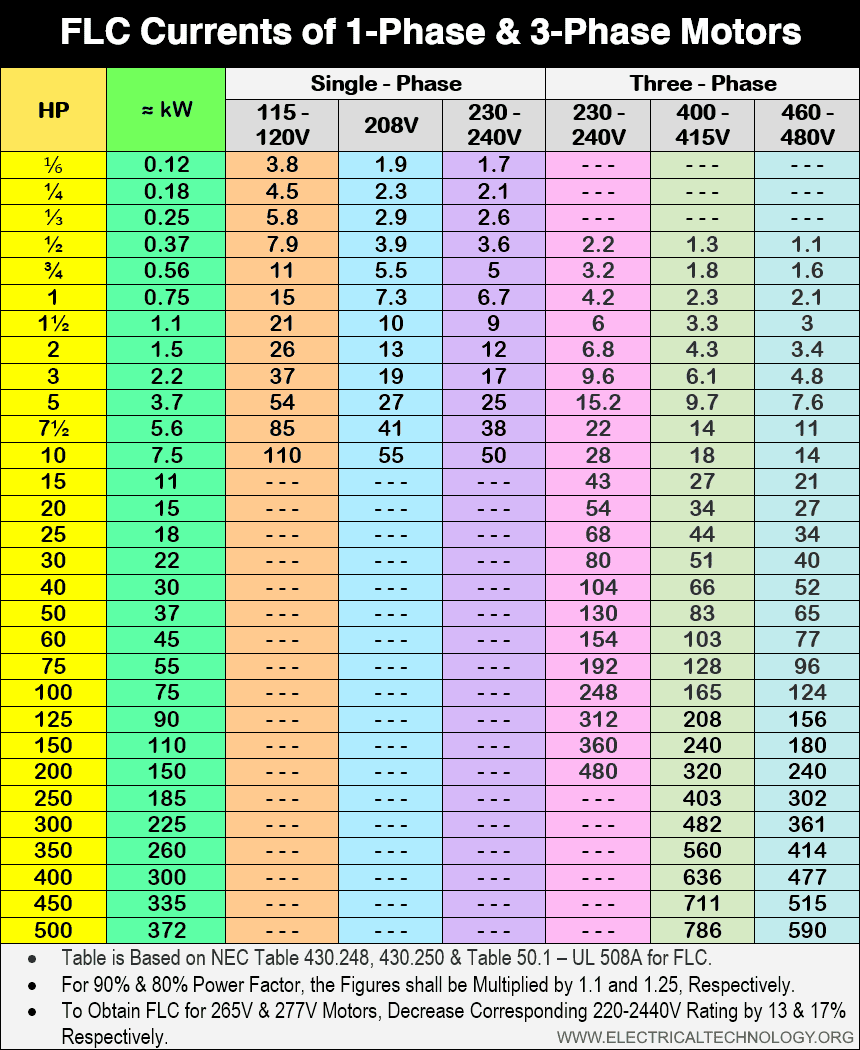
The following table based on NEC Table 430-247, Table 430.240 & UL 508A Table 50.1 shows the values of Full-Load Current (FLC) in amperes for single-phase and three-phase AC induction motors (squirrel-cage & wound rotor).
| FLC Currents of 1-Phase & 3-Phase Motors | |||||||
| HP | ≈ kW | Single – Phase | Three – Phase | ||||
| 115 – 120V | 208V | 230 – 240V | 230 – 240V | 400 – 415V | 460 – 480V | ||
| ⅙ | 0.12 | 3.8 | 1.9 | 1.7 | – – – | – – – | – – – |
| ¼ | 0.18 | 4.5 | 2.3 | 2.1 | – – – | – – – | – – – |
| ⅓ | 0.25 | 5.8 | 2.9 | 2.6 | – – – | – – – | – – – |
| ½ | 0.37 | 7.9 | 3.9 | 3.6 | 2.2 | 1.3 | 1.1 |
| ¾ | 0.56 | 11 | 5.5 | 5 | 3.2 | 1.8 | 1.6 |
| 1 | 0.75 | 15 | 7.3 | 6.7 | 4.2 | 2.3 | 2.1 |
| 1½ | 1.1 | 21 | 10 | 9 | 6 | 3.3 | 3 |
| 2 | 1.5 | 26 | 13 | 12 | 6.8 | 4.3 | 3.4 |
| 3 | 2.2 | 37 | 19 | 17 | 9.6 | 6.1 | 4.8 |
| 5 | 3.7 | 54 | 27 | 25 | 15.2 | 9.7 | 7.6 |
| 7½ | 5.6 | 85 | 41 | 38 | 22 | 14 | 11 |
| 10 | 7.5 | 110 | 55 | 50 | 28 | 18 | 14 |
| 15 | 11 | – – – | – – – | – – – | 43 | 27 | 21 |
| 20 | 15 | – – – | – – – | – – – | 54 | 34 | 27 |
| 25 | 18 | – – – | – – – | – – – | 68 | 44 | 34 |
| 30 | 22 | – – – | – – – | – – – | 80 | 51 | 40 |
| 40 | 30 | – – – | – – – | – – – | 104 | 66 | 52 |
| 50 | 37 | – – – | – – – | – – – | 130 | 83 | 65 |
| 60 | 45 | – – – | – – – | – – – | 154 | 103 | 77 |
| 75 | 55 | – – – | – – – | – – – | 192 | 128 | 96 |
| 100 | 75 | – – – | – – – | – – – | 248 | 165 | 124 |
| 125 | 90 | – – – | – – – | – – – | 312 | 208 | 156 |
| 150 | 110 | – – – | – – – | – – – | 360 | 240 | 180 |
| 200 | 150 | – – – | – – – | – – – | 480 | 320 | 240 |
| 250 | 185 | – – – | – – – | – – – | – – – | 403 | 302 |
| 300 | 225 | – – – | – – – | – – – | – – – | 482 | 361 |
| 350 | 260 | – – – | – – – | – – – | – – – | 560 | 414 |
| 400 | 300 | – – – | – – – | – – – | – – – | 636 | 477 |
| 450 | 335 | – – – | – – – | – – – | – – – | 711 | 515 |
| 500 | 372 | – – – | – – – | – – – | – – – | 786 | 590 |
|
|||||||
Table in Image Format – Click or open in a new tab to enlarge
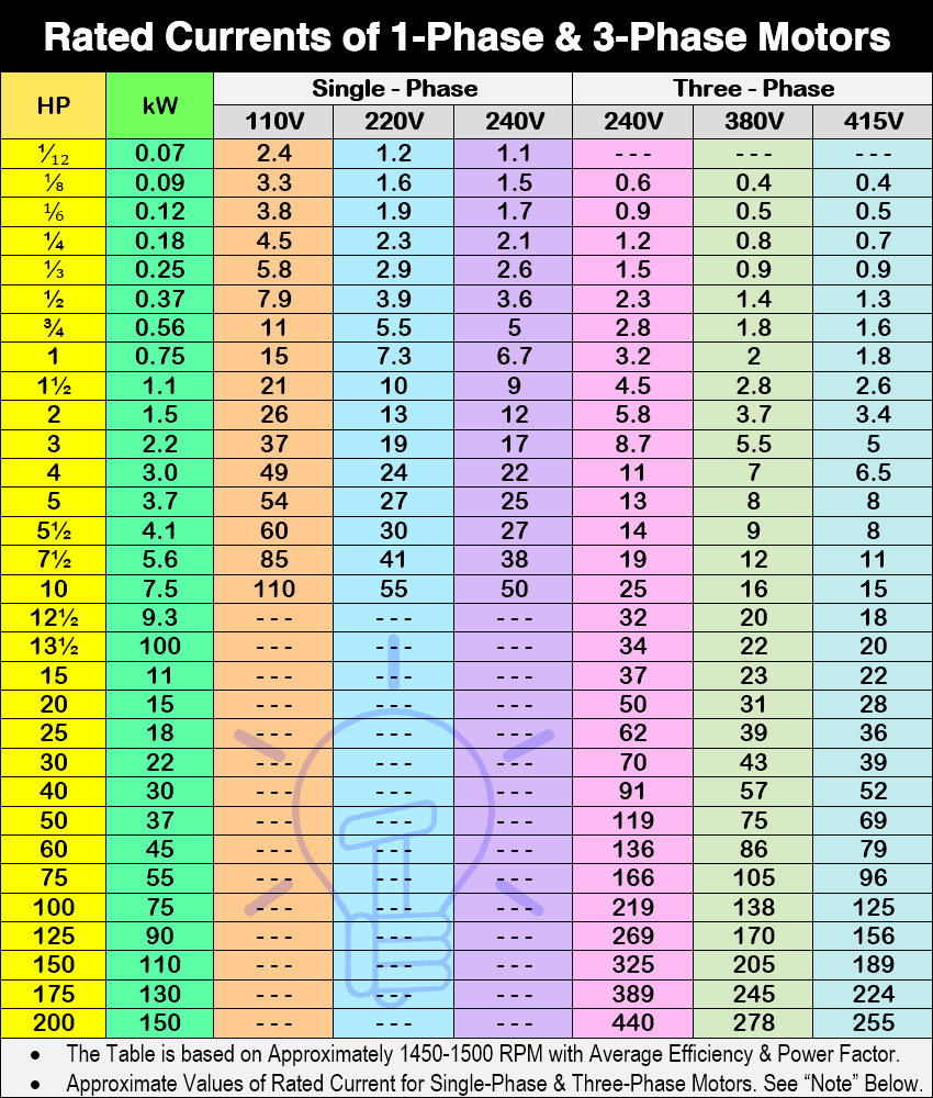
Values of Rated FLA
The following table shows the approximate values of rated full load amperes. These values may vary depending on voltage, efficiency and power factor. The values below are provided by RECON Electrical and R&M Electrical Group. Consult to the manufacturer manual or calculate the actual current from NEC/IEC tables or motor’s nameplate rating.
Click image or open in a new tab to enlarge
Difference Between FLA and FLC
As discussed above, FLA is the actual current a motor draws, whereas FLC is a standardized value used for safety and compliance. The value of full load amperes marked on motor’s nameplate rating is used to determine the size of thermal overload relay setting to withstand the overload conditions while the value of full load current is used to size the wires and cables for motor branch circuit, protection against short-circuit and ground fault, sizing disconnecting means, starters and controllers.
Example:
The values of full load amperes (FLA) printed on a 5HP three phase motor is printed as
- 13.9A at 208V
- 13.4A at 230V
- 6.7A at 460V
While the values of full load current (FLC) for 5HP 3-phase motor mentioned in Table 430.250 are:
16.7 at 208V
15.2 at 230V
7.6A at 460V
Good to Know:
In the past, the UL 508A standard defined FLC as “Full-Load Ampere Rating”. However, in the NFPA 79 standard, the same value was referred to as “Full-Load Current”.
The term “Full-Load Ampere Rating” could cause confusion with FLA (Full-Load Amps), even though it was actually intended to mean FLC.
- Related Post: Difference between AC and DC (Current and Voltage)
Despite the difference in values, the following table shows a comparison between FLA and FLC.
| Feature | FLA (Full Load Amperes) | FLC (Full Load Current) |
| Definition | Actual current drawn by motor at full load | Standardized current value from NEC tables |
| Source | Motor nameplate | NEC tables or similar standards |
| Variability | Varies by motor design/manufacturer | Fixed for given HP and voltage |
| Usage | Used for setting of thermal overload relays and overload protective devices to protect against overload conditions | Used for sizing wires, breakers, disconnecting means, starters, controller with overcurrent protection |
| Accuracy | More accurate (real-world) | Generalized for consistency |
| Example Reference | Thermal relay settings for Overload protection | NEC Tables 430.247 through 430.250 |
Related Posts about Motor Circuits:
- Part 1 – Motor Load Circuits: NEC Terms and Basic Terminologies
- Part 2 – NEC Requirements for Motor Circuits
- Part 3 – Understanding NEMA Motor Nameplate Data
- Part 4 – Calculating Locked Rotor Current (LRC) for Motors
- Part 5 – Sizing Motor Branch Circuit Conductors
- Part 6 – Sizing Motor Feeder Conductors
- Part 7 – Sizing Motor Overcurrent Protection and OCPD’s Devices
- Part 8 – Sizing Motor Feeder Protection
- Part 9 – Sizing Motor Overload Protection
- Part 10 – Overcurrent Protection for Motor Control Circuits
- Part 11 – Sizing Disconnecting Means for Motor & Controller
- Part 12 – Sizing Motor Starter & Contactor – NEMA – NEC
- Part 13 – Sizing Direct Online (DOL) Starters/Contactors for Motors (*Bonus)
- Part 14 – Sizing Star-Delta Motor Starters/Contactors for Motors (*Bonus)
-
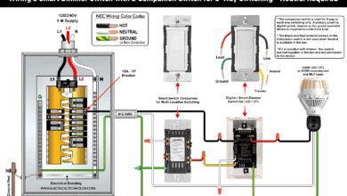
 How to Wire Smart Scene Controller Switch
-
 How to Install a Home and Away Wireless Smart Switch
-
 How to Install a Wire-Free Smart Dimmer Anywhere Companion
-
 How to Wire a Smart Wireless Switch and Anywhere Companion
-
 Wiring a Smart Dimmer Switch Companion with a Digital Dimmer
-
 How to Wire a Digital and Wi-Fi Smart LED Dimmer Switch