Switch & Types of Switches – Construction, Working, & Applications
Different Types of Electromechanical and Electronic Switches
What is a Switch?
A switch is a device which is used to make or break an electric circuit automatically or manually. In other words, an electrical switch is a controlling device, which interrupts the flow of electric current or changes the direction of current in a circuit.
Almost all the electrical and electronic systems use at least one switch to control the ON and OFF operations of the device. In simple words, a switch is used to control the circuit operation by activating or deactivating the whole or certain parts or processes of a connected circuit.
Consider the following basic circuit diagram showing the working and controlling of ON/OFF operation of a light bulb. In fig (left side) the switch is OFF (i.e. the contracts of switch are open) hence the light bulb is OFF. On the right side, the contacts of the switch are closed e.g. switch is ON hence the light bulb is ON and glowing.
As switches play an important role in the controlling systems, this way, you may notice them everywhere even for tiny devices as well as large appliances.
There are multiple applications of switches such as basic light and toggle switches for ON and OFF operations for lighting points, fans, computers, printers, blowers in the residential and commercial buildings, automobiles, computers & mobiles, robotic and sensitive aerospace and military applications.
As there are multiple types of switches which are used for different and designed applications. For example, a single pole switch can be used to control the OFF and ON operation of a light bulb. Similarly, a two pole (2-Way Switch) can be used to control two circuits or two operations of a device. Additionally, Intermediate switches (4-Way switch) are used to control the lighting from two different locations e.g. staircase wiring, corridor & hallway wiring, hostel wiring, godown wiring, tunnel wiring, hospital wiring etc. and so on.
As a switch is used to control the ON & OFF operation of the device, the various types of switches are designed for different applications based on the characteristics, properties and features of switches.
- Related Post: 25 Different Types of Light Switches
Working of an Electrical Switch
The controlling operation of a switch can be defined by its “Pole” and “Throw“. A Pole represents the number of operations controlled by a single switch. The Throw indicates the number of contacts in a switch. For example, the NO (Normally Open) and NC (Normally Closed) are Single Throw which is used to control the circuit by making/breaking contacts of the switch.

Similarly, The intermediate and changeover switches are Double Throw which is used to control the two way operation of the circuit by closing/opening contacts of the switches which is used to divert the flow of current from one circuit to another. In simple words, A Single-Pole-Single Throw (SPST) switch is known for controlling a single circuit (e.g. ON/OFF) per operation. This way, the number of poles and throws are used to represent the controlling process of a switch.
Based on the above explanation, standard number of poles and throws switches are available such as Single Pole, Single Throw (SPST), Double Pole, Double Throw (DPDT), Two Poles, Six Throw (2P6T) and Three Poles, Multiple Throw (3PMT) for selectors and rotary switches etc.
The operation of switch can be defined via two ways i.e. Latching Switches & Momentary Switches.
A Latched Switch (Aka Maintained Switch or Locked Switch) is known to be a switch which maintains its last state until it is automatically or manually forced to change the position. Examples: Push to Make, Push to Break or a common example as a light switch. In short, the latch switch holds its state whether ON or OFF until the new commands initiated.
A Momentary Switch is a switch which maintains its state as long as the button is pressed and actuated. When the pressure is removed, it returns to the previous state both in position and operation. Examples: Push buttons, electric drill, push-down buttons in the blowers etc. In simple words, momentary switch holds the state only when the specific command is presented only.
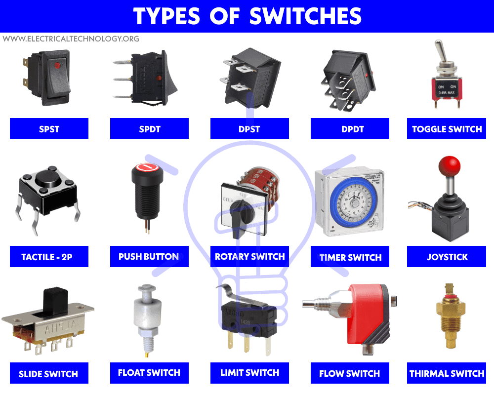
Types of Switches
Generally, Switches can be categorized as.
- Mechanical Switches
- Electrical & Electronic Switches
Both of these types of switches are widely used in electrical and electronics applications where the selection of switch type depends on the system requirements and system needs in which they are going to be incorporated. Switches can also be categories on many different bases and factors. Now let’s discuss them in detail one by one in this article.
Switches Wiring Diagrams:
Types of Electromechanical Switches
Mechanical switch is a switch in which two metal plates (switch contacts) touch each other to make a physical contact for the current to flow through it and separate from each other to interrupt the flow of current.
There are different types of mechanical switches which can be additionally categorized on the basis of power handling capacity, number of poles & throws (SPST, SPDT, DPST, DPDT, DPMT etc), construction and operation, number of contacts, holding state (Locked & Momentary).
The contact material for electromechanical switches is chosen by keeping in mind that the metal oxides which are produced due to corrosion, are mostly insulators and layers of such oxides on the switch plates will hinder the normal operation of the switch. This way, hard drawn copper or forged copper is a good option as contact material which holds and carries the rated current.
Mechanical Switches can be categories on the basis of different factors, design and operation as follow:
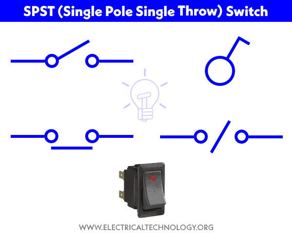
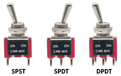
SPST (Single Pole Single Throw)
This is a simple ON/OFF switch commonly found in our homes for lighting circuits and small load appliances as well as computers and devices. It is also called a “One Way” or “Single Way” Switch (known as Two-Way Switch in the US). It controls single operation in a circuit e.g. it makes or breaks the circuit. Generally, the contact of the SPST switch can be either NO (Normally Open) for OFF position or NC (Normally Closed) for ON position.
An open switch indicates a break in the circuit i.e. it stops the flow of current in it. A closed switch represents the circuit is completed and current is flowing through it.
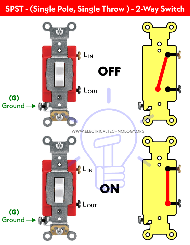
The following fig shows the construction and working of a SPST (Single Pole Single Throw) switch also known as one way switch in UK & IEC following countries while it is knowns as a two-way switch in the US & Canada (NEC & CEC). It has mainly two terminals viz Line IN (as source), Line Out (to the load point) and an extra but optional pin as ground terminal.
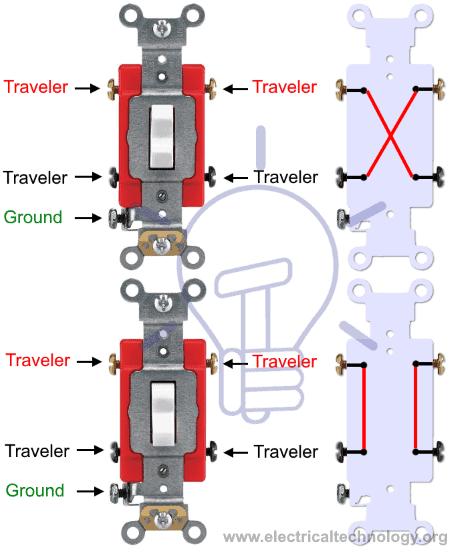
SPDT (Single Pole Double Throw)
SPDT switch has mainly three pins (terminals) and an extra as ground terminal. The input terminal is known and used as “common” which is also called a Two-Way Switch (known as Three-Way Switch in the US). The remaining two terminals are called travelers (output terminals).
A two circuits can be controlled at the same time while using this switch. Because of this functionality e.g. changeover operations, SPDT switches are also known as selector switches.
Other switches related to SPDT are SPCO (Single Pole Changeover) and SPTT (Single Pole Center Off or Single Pole Triple Throw).
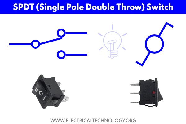
Below is a diagram of construction and operation of Single Pole Double Throw (SPDT) switch also known as 2-way switch.

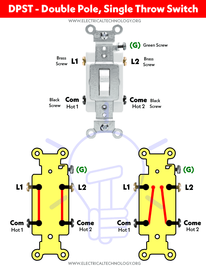
DPST (Double Pole, Single Throw)
DPST switch is basically two SPST switches in one package and can be operated by a single lever. This switch is mostly used where both ground and line need to be broken (or closed) at the same time, same as the operation of a 2-Pole breaker. It short, It has two poles i.e. it can control two circuits (Hot and Neutral) and a Single Throw i.e. it can only make one operation e.g. ON or OFF.
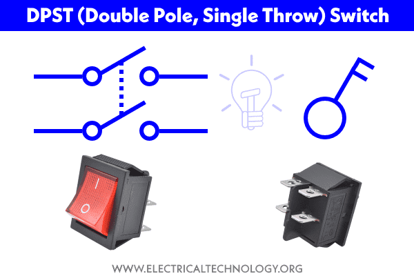
Double Pole, Single Throw switch has four terminal pins i.e. 2 as Input and the rest of 2 as output. DPST switches are used to control a single circuit while both the contacts are needed to be actuated. For example, a DPST switch is used to break both the Line and Neutral wire for the ON & OFF operation of the connected device to it. Both the contacts are open in case of OFF position while both contacts are closed in case of ON position. In simple words, It either switches ON or OFF the two circuits at the same time.
The following fig shows the working operation of a Double Pole, Single Throw Switch rated for 120-277V which make or open both contacts via single operation.
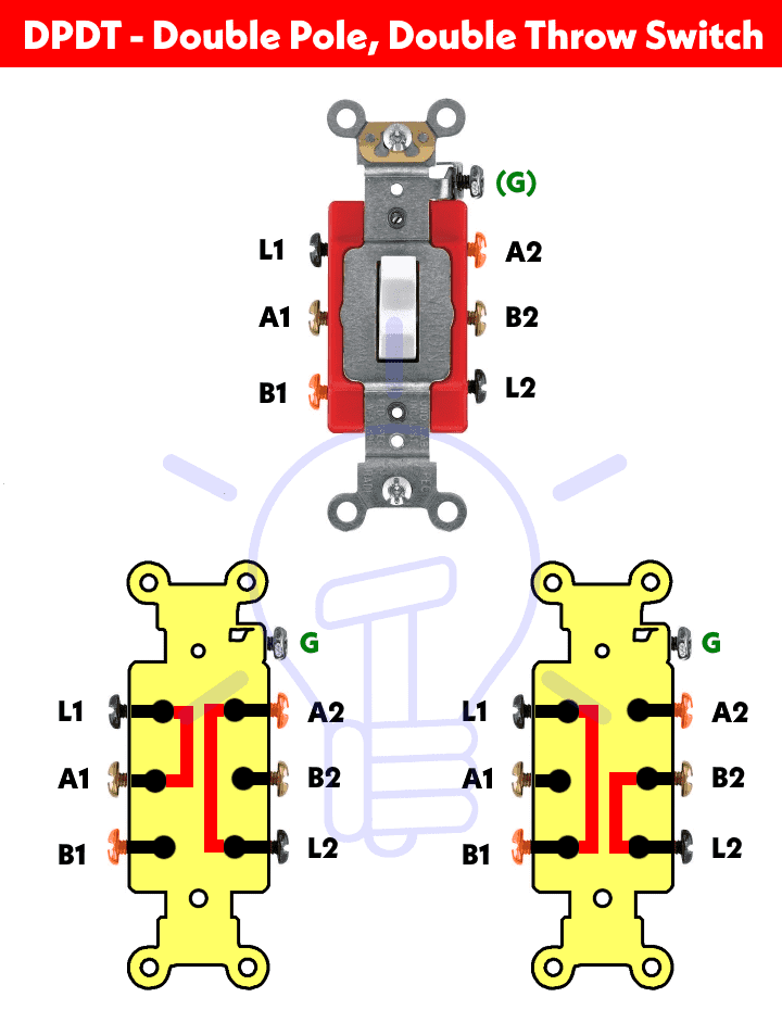
DPDT (Double Pole Double Throw)
This switch is equivalent to two SPDT switches packaged in one unit. This switch has two common pins and four signal pins (total of 6 terminals). Total four different combinations of signals can be applied to the input pins of this switch. Another switch related to DPDT is DPCO (Double Pole Changeover or Double Pole, Centre Off).
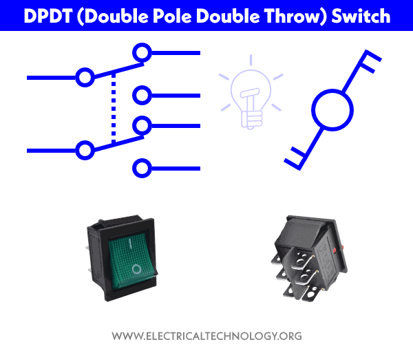
DPDT switches are used to control two different electric circuits at the same time. While it has a common lever for both operations, It can be used for two different operation i.e. ON & OFF positions.
- Related Post: How to Wire Double Pole, Double Throw (DPDT) Switch?
2PMT & 2P6T (Two Pole, Six Throw & Two Pole, Multiple Throw)
DPMT stands for Double Pole Multi Throw and 2P6T abbreviated as 2-Pole, Multi Throw switches. These kinds of switches consist of 2-poles and multiple throw i.e. they can be used to control two independent circuits. These types of switches with a common lever are used as changeover and selectors switches for multiway switching.

Other related switches are 2P4T which is used to control two different circuits while the rest can be controlled and connected to the four throw terminals. 2PMT switch is categorized as rotary and selector switches (discussed in the following section).
Rotary & Selector Switches
Selectors switches are rotary switches with a knob which rotates around its axis and switches and connects the common terminal to many of the output terminals. It is the same as a knob switch in the digital or analog multimeter based on the working principle of demultiplexer, electrical measurement tools and metering, radio bands selectors, channel selectors in a communication system etc.

A rotary switch may have multiple poles and throws for different circuits. The selector switches are available in different ranges i.e. 1P-12 way, 2P- 6 ways (2P6T), 3P-4 Ways & 4P-3 ways etc. It has multiple moving and statutory contacts where the rotating knob is used to divert the switching operation of the switch from one to another.
Related Posts:
Intermediate Switch – 4-Way Switch
Intermediate switch is also known as a four way switch in the US (and Three way switch in the UK & EU). It has four terminals which are used to divert the flow of current from one position to another. These switches are used to control a single appliance such as a light bulb point from different locations. For example, to control a light bulb from two different locations or simply a stair case wiring configuration.
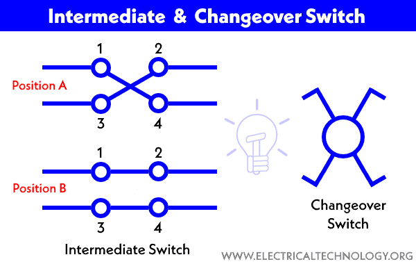
An intermediate switch is also called a changeover or crossover switch.
We have previously published a detailed post about the Intermediate Switch, its construction, working and applications.
The figure below shows the basic configuration and working principle of the intermediate switch.
Toggle Switch
Toggle switches are latched type of switches which are actuated by a lever angled in one or more directions. This switch is stable in state and remains in that state unless or until the lever is pushed in another direction. Most of all household applications (such as lighting control switches) have toggle switch and it can fall into any category as mentioned above e.g. SPST, DPDT, DPST, DPDT etc.
They are available for high current applications up to 30+ amperes and can be used for small current switching operations. The rating, shape and design may vary depending on the circuit requirement and applications.
Slide Switch
As the name shows, a slide switch uses a slider as actuator which slides back and forth to make and break the contacts. The following fig shows the SPDT (single pole double throw) slide switch which is used to control the flow of current in a circuit.

It is used to control the ON and OFF operation of the circuit while the other versions e.g. double poles and throws etc. are used to divert the current flow from one direction to another and control many functions in switching operations.
Push Buttons Switch
As the name suggests, push buttons are momentary switches which are operated by pressings (put a pressure by pushing) it for a while. The spring mechanism for the actuator inside it is used to close or open the circuit for OFF and ON operation.
When a pushbutton switch is pressed, the movable contacts attached to the button make sure to connect the static (stationary or stable) contacts in series to make the circuit. When the pressure is released, contacts of the pins are detached and the circuit operation returns back to the first position either ON or OFF.

They are generally NO, NC or double acting which is used to control two different circuits. Examples of push-button switches are drills, blowers and doorbells etc.
Related Posts:
Limit Switch
A limit switch is operated automatically (by mechanical parts or machine) or manually by an object in control systems. The bumper arm in the switch is used as actuator and when pressed or comes in contact with an object, it changes the direction of the flowing current hence it changes the position and operation of the circuit.
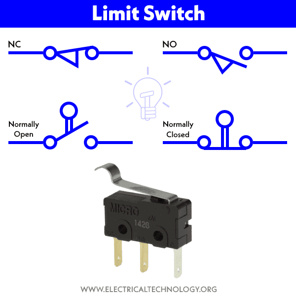
Some examples of limit switches are Push Button Limit Switch which are actuated by the motion of mechanical parts of machines or other objects. Another example is Push Button Double Pole Limit Switch with two poles which is used to control two separate circuits e.g. it breaks one circuit and closes the other one at once.
Related Posts:
Flow Switch
Flow switches are used to detect and control the flow of air or the movement of liquid (such as water, oil etc.) in the connected ducts and pipes. When the air or liquid flows above the limits in the metal or plastic pipes, the snap action by spring mechanism moves the metal arm of the micro switch which leads to makes or breaks the contacts, hence the operation of the system changes.
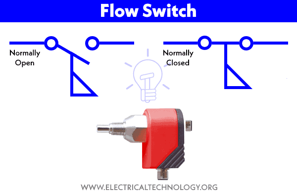
Flow switches can be both Normally Closed and Normally Open which are used to control the air flow or liquids movement in the pipes, ducts and tanks etc.
Float Switch
As the name indicates, a float switch is a floating switch that controls a circuit or machine inside a tank full of liquid (such as a water tank). It detects the level of the liquid and switches ON or OFF when the liquid level rises or falls according to the requirements.

For example, when the level of water falls below the designated line, the contact arms and rod makes the contacts which trigger the circuit, hence, the motor pump (AC or DC Motor) is activated and the water tank again starts to full of the liquid. Similarly, When the water tank is full, the lever disconnects the terminal contacts and motor pumps automatically switched OFF. The whole process is automatic and simultaneous with the help of using a float switch.
Pressure Switch
Pressure switches are used to sense and operate by air or gas under pressure in industrial applications. The different types of (such as metal bellow, piston type and diaphragm operated pressure) switches are widely used in the pneumatic devices and hydraulic systems to measure a range of levels of pressures.
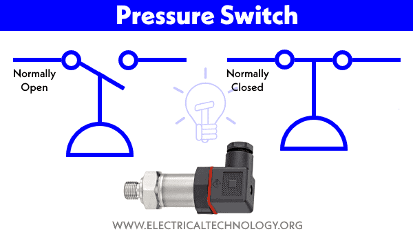
The single pole or double pole pressure switches are operated by pressure detection elements which trigger the contract to open or close to change the position of the system.
Related Posts:
Joystick Switch
Joystick (also known as flight stick or Hat switch) is a switch with a lever connected to it. The lever freely moves where the directional movement connects the different terminals of the switch to control the circuit. The switch contacts can be actuated by moving the stick in the right, left, upper and lover positions.

They are mainly used in gaming controller pads, building machinery, portable control equipment, camera motion control, trucks, excavators and cranes in the industries.
Temperature & Thermal Switches
Thermal and Temperature switches depend on temperature where the heat sensing element (such as bimetallic strip) is bent by thermal expansion i.e. when exposed to the heat. For example, when the temperature rises and crosses the preset level, the bimetallic strip expands and breaks the contact, hence the circuit is open.

When the temperature is reduced below the level, the bimetallic strip shrinks (and returns to the normal position) which leads to making contacts, thus the contacts are connected to close the circuit.
Examples of thermal switches are NC thermal switch, NO thermal switch. mercury glass tube and thermal relays etc. which is used for overload protection of electrical machines.
Timer Switch
Both digital and analog timer switches (also known as timer) are used for time delay for specific applications. A time switch can be configured using the mechanical timer clockwork where it makes or breaks the contact when the (set-up) time runs out and hence ON or OFF the connected circuit from the supply.

Timer switches with the help of contactor and relays are used in power circuits, water heater timer, central heating control, vehicles, sleep timer in the TV sets etc. which operate on timing mechanism. The digital timers (e.g. ST01 Timer or Dusk-dawn timers) are used to control automatic ON-OFF operation of the light fixture based on configured time during the day or Night.
Electrical & Electronic Switches
Electrical and mostly electronic switches are solid-state devices based on semiconductor materials with fast response, accurate operation and small in size as compared to mechanical and electromechanical switches. The solid state switches are based on the basic components such as diodes, SCR, MOSFET, GTO, IGBT, transistors, and relays etc.
Electronic switches have no physical contacts or moving parts and can be automatically operated by electric signals or programmed circuits like microcontroller or microprocessor. They are precise in operation for stability and reliability of the system without noise of switching operation.
They are used in many modern applications such as VFD drives for motors, HVAC & in industrial, automation, automotive, aerospace, robotic and many more commercial applications.
Let’s discuss some of the basic types of electronic switches one by one as follows.
Diode as a Switch
A basic PN junction diode can be used as a switch. The diode in forward bias acts as a closed switch while it acts as an open switch in case of reverse bias.
The PN junction diode is made of Silicon or Germanium (semiconductor materials). When 0.7V (0.3V in case of Germanium) is applied to the diode which is the threshold limit, it operates in High state i.e. forward bias e.g. closed circuit and current starts flowing through it. For high load appliances, power diodes and rectifiers are used for switching operations.
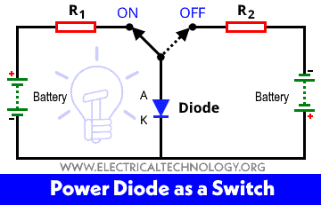
These are the following two switching operations of a diode.
- Forward Bias: If positive signal applied to the Anode terminal and cathode is negative, the diode is forward biased, hence it acts as a closed switch.
- Reverse Bias: If the negative signal applied to the Anode and cathode is positive, the diode is in reverse biased, thus it acts as an open switch.
The following fig shows the diode acting as a basic switch.
BJT Transistors as a switch:
Bipolar Junction Transistors (BJT) can be used as normal switches as they are able to block or pass the flowing of electric current in different modes of operations. For example:
- Saturation Region: In this mode, both of the junctions of the BJT transistors are in forward bias. This region is used for the ON-state of a switch where ic = isat.
- Cut-OFF Region: In the cutoff region, both junctions of a BJT transistor are in reverse bias. Here the BJT works as an OFF-state of a switch where ic = 0.
Let’s see how PNP and NPN transistors work as switches?
NPN Transistor as a Switch
When the input to the inverter is high “+5V”, the NPN transistor is saturated and its output is low “≈0V”. When the input to the inverter is low, the transistor is cut-off and its output is high. In short,
- In the saturation region, it is “ON” like a closed switch
- In the cut-off region, it is “OFF” like an open switch.

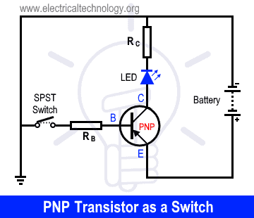
PNP Transistor as a Switch
In this switching circuit, the emitter is connected to the consonant voltage source, the collector is connected to the load (LED) and then ground while the input is the same as PNP Transistor i.e. base terminal. In this configuration, the current flows from the source through the transistor to the load and lastly to the ground.
In short,
- If the Base voltage is negative (ground or low) = The Transistor is ON like Closed Switch.
- If the Base voltage is Positive (high) = The Transistor is OFF like an Open Switch.
Related Posts:
- Simple Touch Sensitive Switch Circuit using 555 Timer & BC547 Transistor
- Clap Switch Circuit Using IC 555 Timer & Without Timer
MOSFET As a Switch:
Similarly to transistors, MOSFETs are widely used as switching devices in power electronics even for high frequencies in MHz.
A MOSFET (Metal Oxide Semiconductor Field Effect Transistor) has three terminals.
- Gate (Input)
- Drain (Output)
- Source (Common)

A MOSFET (P-Channel or N-Chanel) is a voltage controlled device, the ON and OFF operation of a MOSFET as a switching device can be controlled by controlling the Gate to Source (Input) voltage. The switching operation of a MOSFET is as follows:
- Cutoff Region: In this region, the MOSFET remains turned off and there is no drain current ID. When MOSFET is used as a switch, it utilizes this region as OFF-state or Opened Switch.
- Saturation Region: In the saturation region, the MOSFET allows a constant current between source and drain. It acts as the ON-state or Closed Switch.
SCR as a Switch
An SCR stands for Silicon Controlled Rectifier as a thyristor used in high speed switching applications such as rectifiers and power control in the industries. It has three terminals viz Anode, Cathode & Gate.
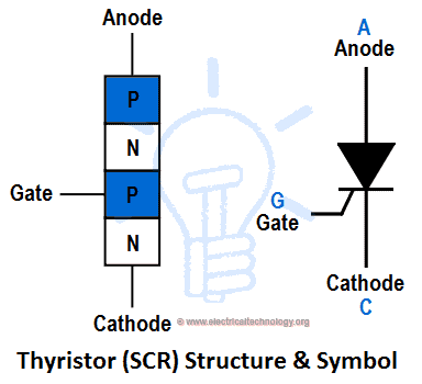
SCR is a four-layered and three junctions unidirectional device i.e. PNPN and J1, J2 & J3. They are also known as PN PN Junction or Latching switches (similar to digital latches) where it can be used as an ON and OFF switch by controlling its gate input voltage and biasing operations.
IGBT as a Switch
IGBT stands for Insulated Gate Bipolar Transistor which is the combination of BJT transistors and MOSFET. It has three terminals namely, emitter, collector and gate. They are used for high speed switching applications.
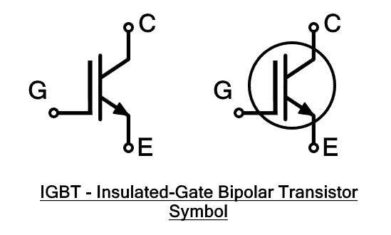
Similar to the the BJT transistors and MOSFET, An IGBT can be used as ON and OFF switch as follows:
- When the VGE is 0v, there is no IC and the device remains switched off like Open switch.
- When the VGE exceeds the threshold limit, the IC starts to increase and the device switches ON.
GTO as a Switch
A GTO stands for Gate Turn OFF is a thyristor based semiconductor and fully controlled unidirectional switching device. It has three terminals namely Anode, Cathode and Gate.
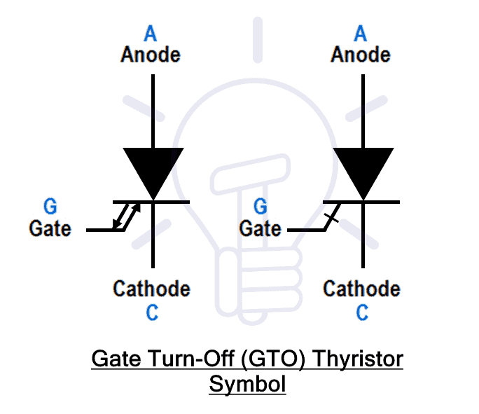
A GTO can be used as a switch for ON and OFF applications where the switching operation can be controlled through the gate terminal.
DIAC as a Switch
DIAC is an acronym which stands for Diode for AC. It is a bidirectional semiconductor uncontrolled switch capable of conducting current in both directions.
It is a two-terminal (namely Main Terminals MT1 & MT2) device made from a combination of two SCRs without the gate terminals.
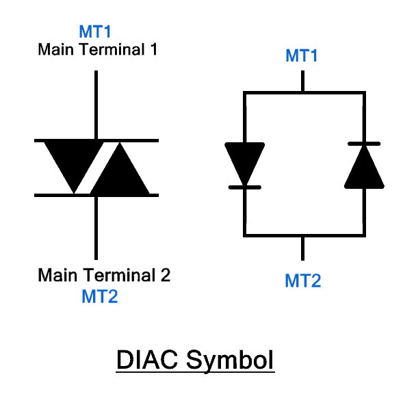
A DIAC starts conduction when the applied voltage increases above the break-over voltage VBO. The main function of a DIAC is to help in triggering and activating TRIAC to perform symmetrical switching operations.
TRIAC as a Switch
TRIAC is abbreviated as “Triode for Alternating Current”. Similarly to the DIAC, It is a bidirectional semiconductor controlled switch capable of conducting current in both directions.

It has three terminals (namely Main Terminals MT1 & MT2 & Gate) having 4-layers device with back to back connected SCRs in a single unit which is used for regulating power in AC circuits, speed control of fans and motors, dimmers in lamps and lights, etc.
DIP Switches
DIP abbreviated as Dual Inline Package is a compact size container where multiple switches are packed together in a dual inline package which is mainly used in breadboards and Printed circuit boards (PCB).
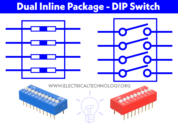
The electromechanical version of a series of switches in a single DIP unit is operated by manually moving the ON and OFF actuator. The digital version automatically toggle the switch and change the operation of the circuit based on the input signals.
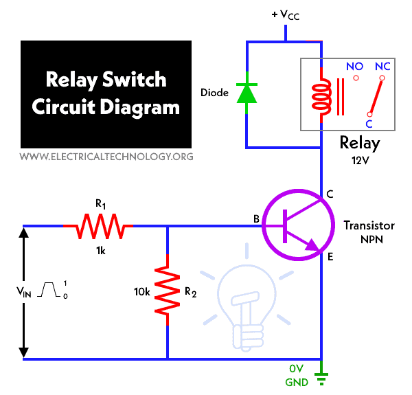
Relay as a Switch
a relay is an electrical switch that controls (switch ON and OFF) a high voltage circuit using a low voltage source. A relay completely isolates the low voltage circuit from the high voltage circuit, hence it may be used as a protective device.
Both electrotechnical and SSR relays are available in multiple poles and throws such as ( SPST NO – Form A, SPST NC – Form B, SPDT – SSR – Form C & DPDT etc).
The working principle for switching operation is different for both solid-state and typical relays such as EMR, SSR, Hybrid, Reed and Thermal relays. The switching properties of a relay are dependent and can be used on the system requirement such as Instant ON SSR Relay, Zero Switching, Peak Switching SSR Relay & Analog Switching SSR Relay.
The following circuit diagram shows the basic relay switch circuit diagram for an electronic switch.
- Related Post: Electronic Relay Switch Circuit – NPN, PNP, N & P Channel Relay Switches with Circuit-diagrams
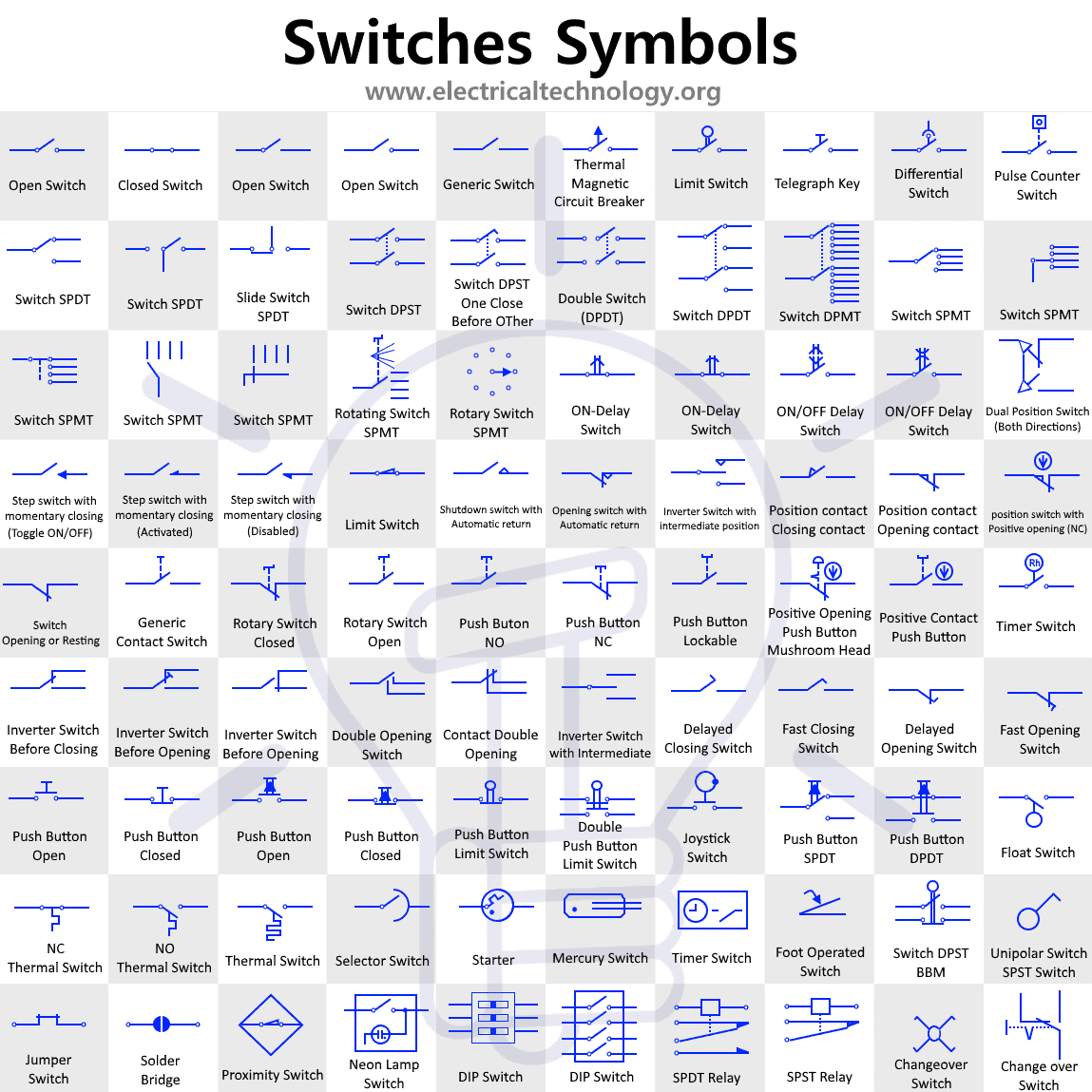
Symbols of Switches
The following chart shows the different symbols used for switches.
Click image to enlarge
This is the basic tutorial about electromechanical switches, electrical switches, and electronics switches, their symbols, construction and working. In the upcoming posts, we will show how to wire switches one by one for different appliances and applications.
Related Posts
- How to Wire Double Switch? 2-Gang, 1-Way Switch – IEC & NEC
- How to a Wire 3-Way Combination Switch and Grounded Outlet?
- How to a Wire Double 3-Way Combination Switch Device?
- Fuse and Types of Fuses
- Types of Electrical Wires and Cables
- Types of Circuit Breakers – Working and Applications
- Types of Resistors and their Applications
- Types of Inductors and Their Applications
- Types Of Capacitors and Their Applications
- Basic Electrical Wiring Tutorials
- Difference Between MCB, MCCB, ELCB & RCD – (RCB or RCCB) Circuit Breakers
- MCB (Miniature Circuit Breaker) – Construction, Working, Types & Uses
- Types of Electrical Drawing and Diagrams
- Switch and Push Button Symbols


i like more information Acb
thanks for the info, please send me a complete notes and photo of various types of electrical switch and their mechanisms of operation
please i need the name of writer of this article. i needed it to reference in my research work
what type of switch do we use in our day to day domestic practice
Thanks for good work, please keep that spirit and God will do you more wonders.
It was dark when I woke. This is a ray of sunshine. types of electrical switches for home
What is the best simple switch to use to operate when power is lost from one and a switches to an alternate source by closing another to where there is a power source or closing another switch to start another source?
In this case, automatic transfer switch (ATS) is the best option.