Single-Phase Induction Motor – Construction, Working, Types & Applications
Single-Phase Induction Motor – Construction, Operation & Types of 1-Phase Induction Motors
The single-phase motors are more preferred over a three-phase induction motor for domestic, commercial applications. Because form utility, only single-phase supply is available. So, in this type of application, the three-phase induction motor cannot be used.
in the following post, we will be showing the construction and different types of 1-phase induction motors with working and applications.
Construction of Single-Phase Induction Motor
A single phase induction motor is similar to the three phase squirrel cage induction motor except there is single phase two windings (instead of one three phase winding in 3-phase motors) mounted on the stator and the cage winding rotor is placed inside the stator which freely rotates with the help of mounted bearings on the motor shaft.
The construction of a single-phase induction motor is similar to the construction of a three-phase induction motor.
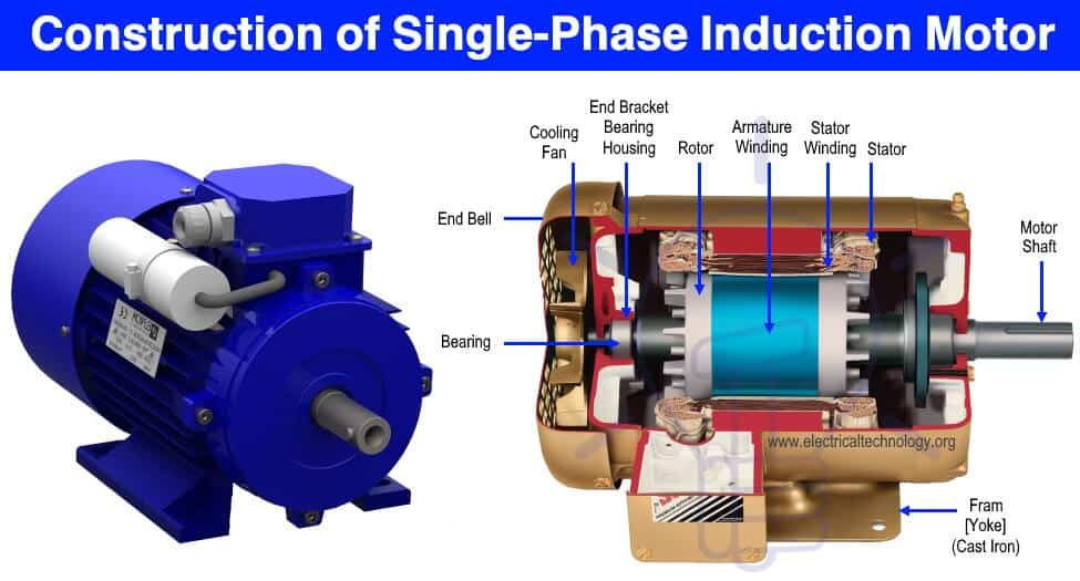
Similar to a three-phase induction motor, single-phase induction motor also has two main parts;
- Stator
- Rotor
Related Post: Synchronous Motor: Construction, Working, Types & Applications
Stator
In stator, the only difference is in the stator winding. The stator winding is single-phase winding instead of three-phase winding. The stator core is the same as the core of the three-phase induction motor.
In a single-phase induction motor, there are two winding are used in stator except in shaded-pole induction motor. Out of these two windings, one winding is the main winding and the second is auxiliary winding.
The stator core is laminated to reduce the eddy current loss. The single-phase supply is given to the stator winding (main winding)
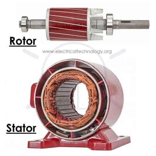
Rotor
Rotor of single-phase induction motor is the same as a rotor of squirrel cage induction motor. Instead of rotor winding, rotor bars are used and it is short-circuited at the end by end-rings. Hence, it makes a complete path in the rotor circuit. The rotor bars are braced to the end-rings to increase the mechanical strength of the motor.
The rotor slots are skewed at some angle to avoid magnetic coupling. And it also used to make a motor run smooth and quiet.
The following fig shows the stator and rotor of a 1-phase induction motor.
Working of Single-phase Induction Motor
Single-phase AC supply is given to the stator winding (main winding). The alternating current flowing through the stator winding produces magnetic flux. This flux is known as the main flux.
Now we assume that the rotor is rotating and it is placed in a magnetic field produced by the stator winding. According to Faraday’s law, the current start flowing in the rotor circuit it is a close path. This current is known as rotor current.
Due to the rotor current, the flux produced around the rotor winding. This flux is known as rotor flux.
There are two fluxes; main flux which is produced by stator and second is the rotor flux which is produced by the rotor.
Interaction between main flux and rotor flux, the torque produced in the rotor and it starts rotating.
The stator field is alternating in nature. The speed of the stator field is the same as synchronous speed. The synchronous speed of the motor depends on the number of pole and supply frequency.
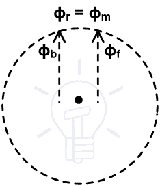
It can represent by two revolving fields. These fields are equal in magnitude and rotating in the opposite direction.
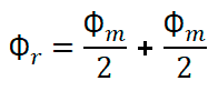
Let say Φm is a maximum field induced in the main winding. So, this field is divided into two equal parts and that is Φm/2 and Φm/2.
Out of these two fields, one field Φf is rotating in an anticlockwise direction and the second field Φb is rotating in a clockwise direction. Therefore, the resultant field is zero.
Φr = Φf – Φb
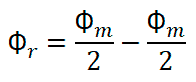
Φr = 0
Now consider the resultant field at different instants.
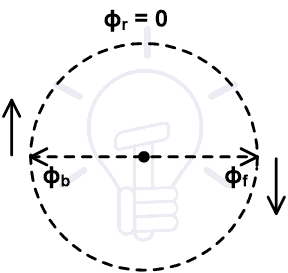
When a motor starts, two fields are induced as shown in the above figure. These two fields are the same magnitude and opposite direction. So, resultant flux is zero.
In this condition, the stator field cannot cut by rotor field and resultant torque is zero. So, the rotor cannot rotate but it produces humming.
Now consider after the rotation of 90˚, both filed are rotated and pointing in the same direction. Therefore, the resultant flux is a summation of both fields.
Φr = Φf + Φb
Φr = 0
In this condition, the resultant filed is equal to the maximum field induced by the stator. Now, both fields rotate separately and it is alternative in nature.
So, both fields cut by the rotor circuit and EMF induced in the rotor conductor. Due to this EMF, the current starts flowing in the rotor circuit and it induces a rotor flux.
Due to the interaction between stator flux and rotor flux motor continues to rotate. This theory is known as Double Revolving Theory or double field revolving theory.
Now, from the above explanation, we can conclude that the single-phase induction motor is not self-starting.
To make this motor self-starting motor, we need stator flux rotating in nature instead of alternating nature. This can be done by various methods.
Single-phase induction motor can be classified according to starting methods.
Types of Single-phase Induction Motors
The single-phase induction motors are classified as;
- Split Phase Induction Motor
- Shaded Pole Induction Motor
- Capacitor Start Induction Motor
- Capacitor Start Capacitor Run Induction Motor
- Permanent Capacitor Induction Motor
Split Phase Induction Motor
In this type of motor, an extra winding is wounded on the same core of the stator. So, there are two windings in the stator.
One winding is known as the main winding or running winding and second winding is known as starting winding or auxiliary winding. A centrifugal switch is connected in series with the auxiliary winding.
The auxiliary winding is highly resistive winding and the main winding is highly inductive winding. The auxiliary winding has few turns with a small diameter.
The aim of auxiliary winding is to create a phase difference between both fluxes produced by the main winding and rotor winding.

The connection diagram is as shown in the above figure. The current flowing through the main winding is IM and current flowing through the auxiliary winding is IA. Both windings are parallel and supplied by voltage V.
The auxiliary winding is highly resistive in nature. So, the current IA is almost in phase with supply voltage V.
The main winding is highly inductive in nature. So, the current IM lags behind the supply voltage with a large angle.
The total stator flux is induced by the resultant current of these two winding. As shown in the phasor diagram, the resultant current is represented as (I). It will create a phase difference between fluxes and resultant flux produces a rotating magnetic field. And the motor starts rotating.
Auxiliary winding only uses to start the motor. This winding is not useful in running condition. When the motor reaches 75 to 80 % of synchronous speed, the centrifugal switch opens. So, the auxiliary winding is out from the circuit. And motor runs on only main winding.
The phase difference creates by this method is very small. Hence, the starting torque of this motor is poor. So, this motor is used in low starting torque applications like a fan, blower, grinder, pumps, etc.
Shaded Pole Induction Motor
As compared to other types of single-phase induction motor, this motor has a different construction and working principle. This type of motor does not require auxiliary winding.
This motor has stator salient pole or projecting pole and the rotor is the same as squirrel cage induction motor. The stator poles are constructed specially to create a rotating magnetic field.
A pole of this motor is divided into two parts; shaded part and un-shaded part. It can be created by cutting pole into unequal distances.
A copper ring is placed in the small part of the pole. This ring is a highly inductive ring and it is known as a shaded ring or shaded band. The part at which shaded ring is paced is known as shaded part of the pole and the remaining part is an unshaded part.
The construction of this motor is as shown in the below figure.

When an alternating supply passing through the stator winding, an alternating flux induced in the stator coil. Due to this flux, some amount of flux will link with shaded ring and current will flow through a shaded ring.
According to Len’z law, the current passing through coil is opposite in nature, and flux produced due to this coil will oppose the main flux.
The shaded ring is a highly inductive coil. So, it will oppose the main flux when both fluxes are in the same direction and it will increase the main flux when both fluxes are in the opposite direction.
So, it will create a phase difference between the main flux (stator flux) and rotor flux. By this method, a phase difference is very less. Hence, the starting torque is very less. It is used in applications like toy motor, fan, blower, record player, etc.
- Related Post: Cable Size Calculation for LT & HT Motors
Capacitor Start Induction Motor
This type of motor is an advanced version of the Split phase induction motor. The disadvantage of split-phase induction is low torque production. Because in this motor, the phase difference created is very less.
This disadvantage compensates in this motor with the help of a capacitor connected in series with auxiliary winding. The circuit diagram of this motor is as shown in the below figure.

The capacitor used in this motor is a dry-type capacitor. This is designed to use with alternating current. But this capacitor is not used for continuous operation.
In this method also, a centrifugal switch is used which disconnects the capacitor and auxiliary winding when the motor runs 75-80% of synchronous speed.
The current through auxiliary will lead the supply voltage by some angle. This angle is more than the angle increased in a split-phase induction motor.
So, the starting torque of this motor is very high compared to the split-phase induction motor. The starting torque of this motor is 300% more than the full load torque.
Due to high starting torque, this motor is used in the applications where high starting torque is required like, a Lath machine, compressor, drilling machines, etc.
- Related Post: Motor Efficiency and How to improve it?
Capacitor Start Capacitor Run Induction Motor
In this type of motor, two capacitors are connected in parallel with series in auxiliary winding. Out of these two capacitors, one capacitor is used only for starting (starting capacitor) and another capacitor is connected permanently with the motor (running capacitor).
The circuit diagram of this figure is as shown in the below figure.
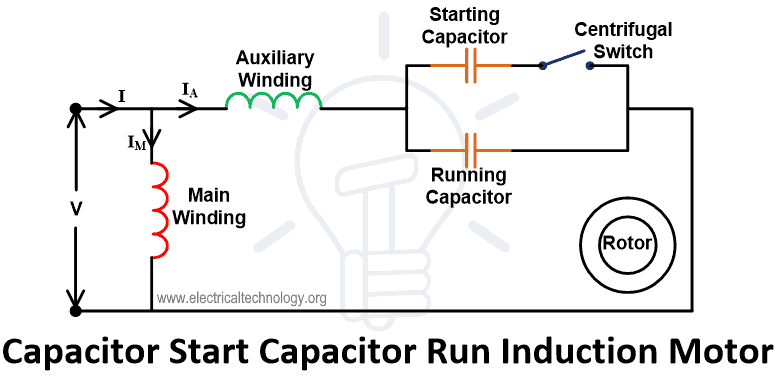
The starting capacitor has high capacitance value and a running capacitor has low capacitance value. The starting capacitor is connected in series with a centrifugal switch that will open when the speed of the motor is 70% of synchronous speed.
During running conditions, both running winding and auxiliary winding connected with motor. The starting torque and efficiency of this motor are very high.
Therefore, this can be used in the application where high starting torque is required like a refrigerator, air conditioner, ceiling fan, compressor, etc.
Permanent Capacitor Induction Motor
The low-value capacitor is connected constantly with the auxiliary winding. Here, the capacitor has low capacitance.
The capacitor is used to increase the starting torque but it is low compared to the capacitor start induction motor.
The circuit diagram and phasor diagram of this motor is as shown in the below figure.

The power factor and efficiency of this motor are very high and also it has a high starting torque that is 80% of full load torque.
This type of motor is used in the application like an exhaust fan, blower, heater, etc.
Applications of Single Phase Induction Motors
Single phase motors are not self starting and less efficient than three phase induction motor and available in 0.5HP to 15HP and still they are widely used for multiple purposes such as:
- Clocks
- Refrigerators, freezers and heaters
- Fans, table fans, ceiling fan, exhaust fans, air coolers and water coolers.
- Blowers
- Washing machines
- machine tools
- Dryers
- Type writers, photostats and printers
- Water pumps and submersible
- Computers
- Grinders
- Drilling machines
- Other Home instrument, equipment and devices etc.
Related Posts:
- Difference Between Single Phase & Three Phase Induction Motor
- Why Motor rated in kW instead of kVA?
- Direct Online Starter – DOL Starter Wiring Diagram for Motors
- Electrical Transformer – Construction, Working, Types and Applications
- Alternator or Synchronous Generator: Construction, Working, Types & Applications
- Induction Generator or Asynchronous Generator: Construction & Working
- Speed Control of DC Motor – Voltage, Rheostatic & Flux Control Methods
- AC Drive – Working and Types of Electrical Drives & VFD
- DC Drive – Working and Types of DC Drives
- Three Phase Motor Power & Control Wiring Diagrams
- Electric Motors Symbols
- Applications of Electric Motors


Could you share me the file please?
Due to do my AM2 when college re-opens you have any tips please