How to Wire 120V Water Heater Thermostat – Non-Simultaneous?
Single Phase 120V Non-Continues Dual Element Water Heater Thermostat Wiring
In the electric water heaters and thermostat wiring and installation series, we will be showing that how to wire and install a non-simultaneous (non-continuous) dual element water heater and thermostat for 120V AC single phase (US) and 230V AC single phase (EU/UK).
- Related Heater Wiring: How to Wire a Single Element Water Heater and Thermostat?
Non-Simultaneous or Non-Continuous Operation of Water Heater
Non continuous or non-simultaneous heating elements are dependent on each other i.e. both elements are not “ON” at the same time. In other words, the upper heating element will turn “ON” and heat the top of the water tank first. The redundant or lower element will turn on when cold water enters the tank. This is an automatic process due to the thermostat wiring connection where the lower thermostat and element is controlled by the upper thermostat which automatically turns on the lower element when needed..
This way, both elements won’t operate at the same time. In very simple words, either the upper or lower heating element is “ON” or both are “OFF”. Keep in mind the same thermostats can be wired for simultaneous or continuous operation where both elements are operational at the same time in case of more hot water consumption. Don’t worry, we will cover these kinds of operations in our next posts.
- Related Heater Wiring: How to Wire 120V Simultaneous Water Heater Thermostat?
120V AC Single Phase Dual Element Water Heater Thermostat Wiring
In non-simultaneous water heater thermostat wiring, the Phase or Hot “L” is connected to the left terminal L1 of the upper thermostat and Neutral “N” is connected to the right terminal L3. Two wires are outgoing from L4 as neutral to the upper and lower heater elements. The upper heating element is connected through T2 and L4.
The lower thermostat is connected through T4 of the upper thermostat which is wired to the terminal “1” of the lower thermostat. The second terminal “2” is connected to the lower heating element.
Since there are two heating elements each rated about 1900 watts, the total wattage rating of this heater is 3800 watts. We will be using the breaker and switch sizes for half rating of the total wattage i.e. 1900 watts as only one element is operating at a time.
- Related Water Heater Wiring: How to Wire 240V Simultaneous Water Heater Thermostat?
Click image to enlarge
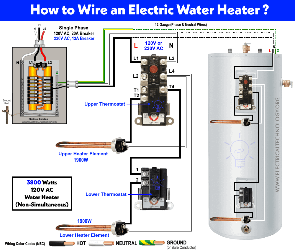
Now in case if 120V AC, a 20A circuit breaker and single way switch is suitable for both wires having 12 gauge size. How? Let’s see as follow.
- Total wattage: 3800 / 2 = 1900 Watts.
- Load Current = 1900 / 120V = 15.83A.
Breaker Size should be 1.25 (125%) of the load current:
15.83 x 1.25 = 19.79A
Another way, the safe limit of circuit breaker is 80% (0.8), this way 20A x 0.8 = 16 Amp which is safe for load current.
This way, a 20A circuit breaker for over current protection is suitable in case of dual element non-continuous water heater circuit for 120V AC.
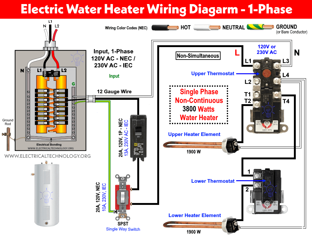
230V AC Single Phase Dual Element Water Heater Thermostat Wiring
The following wiring diagram shows the same connection as above despite the breaker and switch size rating according to the NEC and IEC. The wiring connection and working is the same as above for 120V configuration.
Click image to enlarge
Non-Simultaneous Thermostat Operation
In this case, the power enters through L1 and L3 (upper thermostat) which operates the upper element. Once the temperature in the upper portion of the water tank rises to the desired (according to the rating i.e. 150° to 180°F) , the bimetallic strip in the upper thermostat releases and separates the T2 from T1 and connects T1 to the T4 terminal. This way, the upper element is turned off and power continues to the lower element through L4 and T4.
This process is shown in the following fig. fig (a) shows the upper element operation while fig (b) shows the lower thermostat and element operation when they are active.
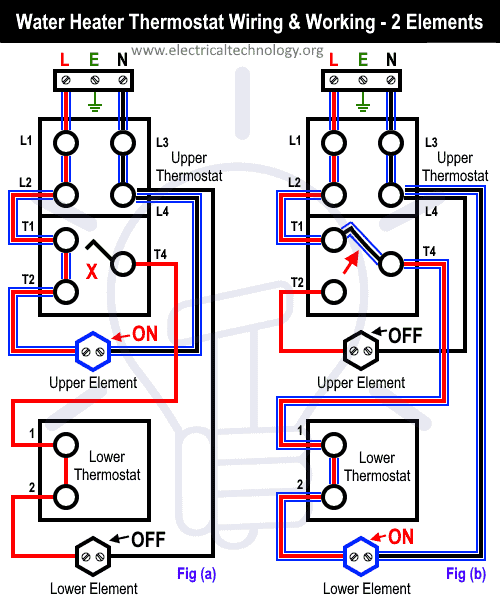
Note: In the above diagram, the Red color illustrates the Line or Phase wire and Black color shows the Neutral Wire in the above figures. You may follow your regional wiring color codes i.e. IEC or NEC.
Related Posts:
- How to Wire 3-Phase Simultaneous Water Heater Thermostat?
- How to Wire 3-Phase Non-Simultaneous Water Heater Thermostat?
Warning:
Related Wiring Installation Tutorials
- How to Wire 120V & 240V Main Panel? Breaker Box Installation
- How to Determine the Number of Circuit Breakers in a Panel Board?
- How to Size a Load Center, Panelboards and Distribution Board?
- How to Determine the Right Size Capacity of a Subpanel?
- Single Phase Electrical Wiring Installation in Home – NEC & IEC
- Three Phase Electrical Wiring Installation in Home – NEC & IEC
- How to Wire Auto & Manual Changeover & Transfer Switch – (1 & 3 Phase)
- How to Connect a Portable Generator to the Home Supply – 4 Methods
- How to Wire Analog and IP PTZ Camera with DVR and NVR?
- How to Wire Different Fire Alarm Systems – Conventional & Addressable
- Even More Residential Wiring Installation Tutorials


Thnx very much for the service that your providing to us sincerely
Valuable information
.
Nice explanation for a newbie. Now I understand how it works. Was thinking both elements came on at same time.