How to Wire 240V Water Heater Thermostat – Non-Continuous?
Single Phase 240V and 230V Non-Simultaneous Dual Element Water Heater Thermostat Wiring
In the electric water heaters and thermostat wiring and installation series, we will be showing that how to wire and install a non-continuous (non-simultaneous) dual element water heater and thermostat for 240V AC single phase (US) and 230V AC single phase (UK/EU).
As we have discussed before about the continuous (simultaneous) and non-continuous (non-simultaneous). In simultaneous wiring, both the water heating elements are operated at the same time while in non-simultaneous wiring, only one heating element is operational at a time and second one “ON” when the first one completes the heating job and disconnected from the power supply automatically by thermostat wiring configuration.
In this post, we will be showing a 10kW dual element (5kW heating element each) with 240V AC supply from 120/240V main panel and 7kW dual element (3.5k heating element each) for 230V AC and 240V AC thermostat wiring for non-continuous operation i.e. only one heating element will be operational at a time.
Related Water Heater Wiring:
- How to Wire 240V Simultaneous Water Heater Thermostat?
- How to Wire a Single Element Water Heater and Thermostat?
240V AC Non-Simultaneous Dual Element 5kW Water Heater Thermostat Wiring
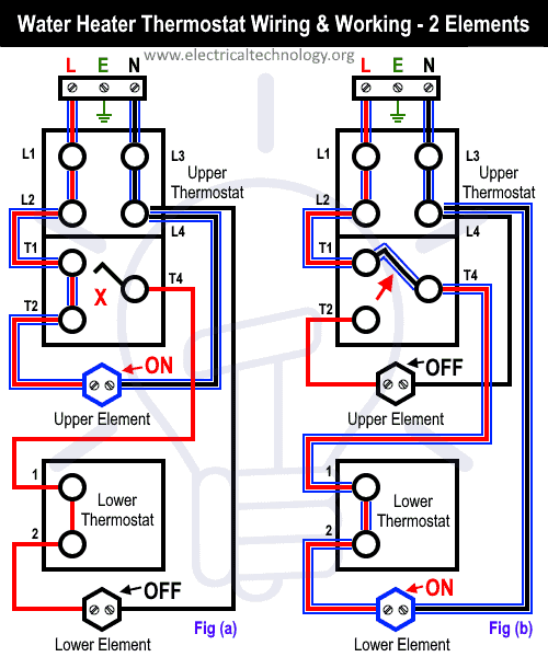
As like in previous wiring diagrams, The upper thermostat is connected to the single phase 240V AC supply through a 30 amp circuit breaker. The Line (L1) as hot wire is connected to the thermostat right terminal L3. Two wires (blue and red) outgoing from thermostat terminal L4 to the first end of upper and lower heating elements while terminal T4 of upper thermostat is connected to the lower thermostat terminal 1 and T2 of upper thermostat is connected to the second terminal of heating element. Finally, the “2” terminal of the lower thermostat is connected to the second terminal of the lower heating element.
Click image to enlarge Blue
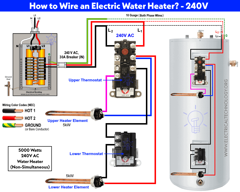
The non-simultaneous thermostat operation will automatically switch off the upper heating element after successful operation and connect the lower one. The following diagram shows it perfectly.
Since there are two heating elements each rated about 5000 watts, the total wattage rating of this heater is 10000 watts. We will be using the breaker and switch sizes for half rating of the total wattage i.e. 10kW as only one element is operational at a time.
Related Water Heater Wiring:
- How to Wire 120V Simultaneous Water Heater Thermostat?
- How to Wire 120V Water Heater Thermostat – Non-Simultaneous?
Now in case of 240V AC, a 30A circuit breaker is suitable for both wires having 10 gauge size as followed by the following calculations.
- Total wattage: 10kW / 2 = 5kW.
- Load Current = 5kW / 240V = 20.83A.
Breaker Size should be 1.25 (125%) of the load current:
20.83 x 1.25 = 26A
Another way, the safe limit of circuit breaker is 80% (0.8), this way 30A x 0.8 = 24 Amp which is safe for load current.
This way, a 30A circuit breaker for over current protection is suitable in case of 5kW dual element non-continuous water heater circuit for 240V AC.
Related Heater Wiring:
- How to Wire 3-Phase Simultaneous Water Heater Thermostat?
- How to Wire 3-Phase Non-Simultaneous Water Heater Thermostat?
230V & 240V AC Non-Continuous Dual Element 3.5kW Water Heater Thermostat Wiring
The following 7kW (each heating element of 3.5kW) has the same wiring connection as above for 5kW thermostat wiring despite a 20A single way switch has been used in 230V AC for ON/OFF operation. Keep in mind that these switches are not suitable for 240V two lines supply.
In the following water heater wiring diagram of 3500 watts non-continuous operation, both wires from the main distribution board are shown as “L” and “N” for 230V AC supply and L1 and L2 for 240V two lines AC supply.
Click image to enlarge

Note: Red color illustrates the Line or Phase wire and Black color shows the Neutral Wire in the above figures. You may follow your regional wiring color codes i.e. IEC or NEC.
Related Heater Wiring:
- How to Toggle Electric Water Heater Between 120V and 240V?
- How to Control Electric Water Heater using Switches?
Related Wiring Installation Tutorials
- How to Wire 120V & 240V Main Panel? Breaker Box Installation
- How to Determine the Number of Circuit Breakers in a Panel Board?
- How to Size a Load Center, Panelboards and Distribution Board?
- How to Determine the Right Size Capacity of a Subpanel?
- Single Phase Electrical Wiring Installation in Home – NEC & IEC
- Three Phase Electrical Wiring Installation in Home – NEC & IEC
- How to Wire Auto & Manual Changeover & Transfer Switch – (1 & 3 Phase)
- How to Connect a Portable Generator to the Home Supply – 4 Methods
- How to Wire Analog and IP PTZ Camera with DVR and NVR?
- How to Wire Different Fire Alarm Systems – Conventional & Addressable
- Even More Residential Wiring Installation Tutorials


Hi,
I wanted to point out an error that was made referring to the 230/240 V non-continuous Water Heater wiring diagram. In the diagram you have placed an N, referring to L2 as a neutral, when in fact L2 is at line voltage. You also included this caption underneath the diagram.
Note: Red color illustrates the Line or Phase wire and Black color shows the Neutral Wire in the above figures. You may follow your regional wiring color codes i.e. IEC or NEC.
According to the NEC the black and red wire are hot wires in this case at a potential of 120v each. The neutral wire is white and, in this diagram, there is no neutral wire.
I just wanted to point this out because it is confusing.
I enjoyed visiting your site and I got the information I needed to fix my water heater.
Thank you
Greg
Hi Greg,
If you see in the following diagram “https://www.electricaltechnology.org/wp-content/uploads/2020/01/230V-240V-AC-Non-Continuous-Dual-Element-3.5kW-Water-Heater-Thermostat-Wiring.png”
We have clearly mentioned “L1 and L2 = Hot 1 and Hot 2 (No Neutral) for 240V – USA – NEC.
For 230 V IEC – We have used the Red and Black for Phase and Neutral respectively (Old wiring color code) New wiring color codes for 230V single phase AC are Brown and Sky Blue.
Let me know if you have more questions?
Thanks