Schematic Diagram of Digital Voltmeter With LCD Display Using AT89C51 Microcontroller With Source Code
A digital voltmeter is an electronic instrument that measures the voltage of an electrical signal. It is used in various applications, including in the field of electronics, power systems, and automation. In this article, we will discuss the implementation of a digital voltmeter using 8051 microcontroller.
The 8051 microcontroller is a widely used microcontroller, which is suitable for a variety of applications. It has 4KB of on-chip ROM, 128 bytes of on-chip RAM, 32 I/O pins, and a 16-bit timer. The microcontroller can be programmed in assembly language or in a high-level language such as C.
The microcontroller has several features that make it ideal for use as a digital voltmeter, such as a built-in ADC (Analog-to-Digital Converter) and an 8-bit timer.
If you’re interested in a compact and mini Digital Voltmeter described in the circuit below for general maintenance, troubleshooting and testing electrical/electronic components, you can get one at the following link.
Related Posts:
- Circuit Diagram of Digital Voltmeter Using Using ICL7107
- Circuit Diagram of Voltmeter, Continuity & Digital LCD Circuit Tester
Components Required
To build a digital voltmeter using 8051 microcontroller, we need the following components:
- 8051 microcontroller (AT89C51).
- LCD display – (7 Segment 4 Digit).
- Analog-to-Digital Converter (ADC0804 IC).
- Voltage Sensor (25V).
- Battery or DC Adaptor.
- Microcontroller Programming Board.
- Crystal Oscillator = 12MHz.
- 3 Nos. of Resistors = 10kΩ.
- 4 Nos. of Capacitors = 2 of 33pF, 1 of 150pF and forth one as 10µF/16V.
Circuit Diagram
Click image to enlarge

Overview of the Circuit:
The circuit for the digital voltmeter using the 8051 microcontroller consists of several components such as the 8051 microcontroller, LCD display, voltage divider network, and a few other passive components. The voltage divider network is used to reduce the voltage to a level that can be read by the microcontroller.
Voltage Divider Circuit (ADC0804 IC)
The voltage divider circuit is used to increase the ADC range of input signal to 25V or step down the input voltage to a safe level, which can be measured by the microcontroller. The potentiometer is used to adjust the voltage range of the voltmeter. The ADC is used to convert the analog voltage signal into a digital signal, which can be displayed on the LCD display.
The voltage divider circuit consists of two resistors, R1 and R2, connected in series. The input voltage is applied across the series combination of R1 and R2, and the output voltage is taken across R2. The ratio of R2 to (R1+R2) determines the output voltage. We can adjust the output voltage range by varying the values of R1 and R2.
The ADC converts the analog voltage signal into a digital signal by comparing the input voltage with a reference voltage. The resolution of the ADC depends on the number of bits used in the converter. For example, an 8-bit ADC can measure a voltage range of 0-5V with a resolution of 19.53 mV per step.
The software for the digital voltmeter is written in assembly language or in C language. The software reads the voltage signal from the ADC, converts it into a digital value, and displays it on the LCD display. The software can also be programmed to implement additional features, such as peak voltage measurement, voltage averaging, and voltage logging.
To summarize, a digital voltmeter using 8051 microcontroller is a simple and cost-effective solution for measuring voltage signals in various applications. It requires a voltage divider circuit, an ADC, a potentiometer, and an LCD display. The microcontroller can be programmed in assembly language or in C language to implement additional features.
Working of the Circuit:
The voltage divider network is made up of two resistors in series. One of the resistors is a potentiometer that can be adjusted to calibrate the voltmeter. The output of the voltage divider network is connected to the analog input pin of the microcontroller. The microcontroller uses its built-in ADC to convert the analog voltage to a digital value.
The digital value is then displayed on the LCD display. The LCD display is connected to the microcontroller through a digital interface. The microcontroller sends the digital value to the LCD display, which then displays it in a readable format.
The programming for the microcontroller involves initializing the ADC, reading the analog voltage, converting it to a digital value, and then sending it to the LCD display. The microcontroller continuously reads the voltage and updates the display.
How to Program the Microcontroller AT89C51 for Digital Voltmeter?
The process described above outlines the steps to test a circuit that has already been programmed and built (Circuit diagram and project code is given below). Here are the steps compared and explained in more detail:
- Burn the program to the AT89C51 microcontroller: This step involves using a programmer to transfer the compiled program code to the microcontroller. The program code is typically written in a programming language such as C or assembly language. The program code contains the instructions that the microcontroller will execute to perform the desired functionality.
- Connect the circuit: After the program has been burned onto the microcontroller, the circuit can be assembled using the circuit diagram as a guide. The circuit includes the at89c51 microcontroller, voltage sensor, and display components. The connections should be made carefully to ensure that the circuit is wired correctly and all components are properly powered.
- Connect a voltage source: The voltage source is connected to the input of the voltage sensor. It is important to ensure that the maximum analog input voltage is less than 25V DC to prevent damage to the circuit.
- Connect a digital multimeter: A digital multimeter is connected to the input terminals of the voltage sensor. The multimeter is used to verify that the voltage readings displayed on the LCD and multimeter are the same or very similar.
- Switch on the board supply: The power supply for the circuit is switched on. This provides power to the microcontroller and other components of the circuit.
- Observe the displays: Both the LCD and digital multimeter displays should show the same or very similar voltage readings. This indicates that the voltmeter is working properly.
- Vary the input voltage: If possible, the input voltage can be slowly varied to verify that the voltmeter continues to display accurate readings.
- Switch off the board supply: The power supply for the circuit is switched off to power down the components.
Programing Code:
#include
#define lcd P3
#define dat P2
sbit rs=P1^6;
sbit e=P1^7;

void delay (int);
void display (unsigned char);
void cmd (unsigned char);
void init (void);
void string (char *);
void intro (void);
char i=0;

void delay (int d)
{
unsigned char i=0;
for(;d>0;d--)
{
for(i=250;i>0;i--);
for(i=248;i>0;i--);
}
}
void cmd (unsigned char c)
{
lcd=c;
rs=0;
e=1;
delay(10);
e=0;
}
void display (unsigned char c)
{
lcd=c;
rs=1;
e=1;
delay(10);
e=0;
}
void string (char *c)
{
while(*c)
{
display(*c++);
}
}
void init (void)
{
cmd(0x38);
cmd(0x01);
cmd(0x0c);
cmd(0x80);
}
void intro (void)
{
string(" Electronics ");
cmd(0xc0);
string(" Hub ");
delay(2000);
cmd(0x01);
string(" Digital ");
cmd(0xc0);
string(" Voltmeter ");
delay(2000);
cmd(0x01);
cmd(0x80);
}

void main()
{
unsigned int temp=0;
unsigned int temp1=0;
float val=0.0;

init();
intro();
dat=0xff;
while(1)
{
if(i==0)
{
string(" Volts - ");
i++;
}
val=dat*0.02; // 0.02 is resolution of adc
val=val/0.2; // 0.2 is nothing but (R2/(R1+R2)) resistor values in the voltage sensor
cmd(0x89);
if((val>=1.0) && (val<10.0)) { display(' '); temp=val*1000; temp1=((temp/1000)+48); display(temp1); display('.'); temp1=(((temp/100)%10)+48); display(temp1); } else if((val>=10.0) && (val<100.0))
{
temp=val*100;
temp1=((temp/1000)+48);
display(temp1);

temp1=(((temp/100)%10)+48);
display(temp1);

display('.');

temp1=(((temp/10)%10)+48);
display(temp1);
}
else
{
display(' ');
string("0.0");
}
delay(1000);
}
while(1);
}
Advantages of Digital Voltmeter using 8051 microcontroller:
1. The digital voltmeter is more accurate and precise than analog voltmeters.
2. The microcontroller can be programmed to perform other tasks besides measuring voltage.
3. The digital display is easy to read and interpret.
4. The circuit is simple and inexpensive to build.
5. The voltmeter can be powered using batteries, making it portable and easy to use in the field.
Limitations
- This circuit can only be used to measured low voltage applications (up to 25V).
- The input signal of analog voltage should be between 0V to 5V.
- This system is capable of measuring only a single analog input value at any given time.
Want one Mini Digital DC Voltmeter for General purpose Applications? Get One below
Related Posts:
- USB Propeller LED Fan Clock – Circuit Diagram & Project Code
- Circuit Diagram of Cable and Wire Tester Circuit Diagram
- How to Test a Capacitor by Digital & Analog Multimeter – 6 Methods
- How to Test a Relay? Checking SSR & Coil Relays
- How to Test a Diode using Digital & Analog Multimeter – 4 Ways.
- How to Test & Fix the Printed Circuit Board (PCB) Defects?
- How to Test a Transistor using Multimeter – NPN & PNP – 4 Ways
- How to test a battery with Test meter?
- How to find The value of Burnt Resistor ( By three handy Methods )
- How To Locate Faults In Cables? Cable Faults, Types & Causes
- Smart Home Automation System – Circuit and Source Code
- Soldering Iron Temperature Controller
- Automatic LED Emergency Light Circuit
- Automatic Night Lamp Using Arduino
- Automatic Bathroom Light Switch Circuit Diagram and Operation
-
 How to Wire Smart Scene Controller Switch
-
 How to Install a Home and Away Wireless Smart Switch
-
 How to Install a Wire-Free Smart Dimmer Anywhere Companion
-
 How to Wire a Smart Wireless Switch and Anywhere Companion
-
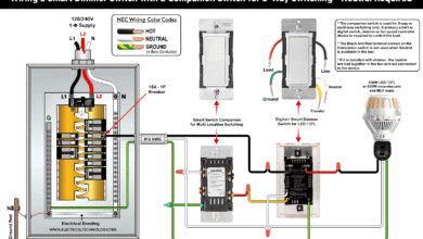
 Wiring a Smart Dimmer Switch Companion with a Digital Dimmer
-
 How to Wire a Digital and Wi-Fi Smart LED Dimmer Switch