How To Locate Faults In Cables? Cable Faults, Types & Causes
Cable Faults, Types, Causes and How to locate faults in Cables via different Tests
Introduction to Faults in Cables
When electrical energy is generated in the generations’ stations, it is distributed to the different loads, i.e. cities, towns and villages for consumption then. The process involves stepping up the voltage to minimize the loss of energy in the form of heat. The stepped up voltage is distributed to grid stations where it is stepped down for distribution to the local transformers where it is finally stepped down and distributed to the consumers.
Distribution of the electrical energy is done via electrical cables. The cables are either insulated or uninsulated. The choice of using insulated or uninsulated (Overhead lines or Underground) cables mostly come into play when energy is to be conveyed in the underground installation process.
Unlike the insulated cables, faults in uninsulated cables are easily detected as the most common fault associated with such type of cable is cut and break in the cable or wire conductors.
In insulated cables especially the multicore cables, the faults are of different types and have many causes.
Before we discuss how to locate these commonly met faults, let’s see what the cable faults are and the possible causes and locating of these faults.
Types of Cable Faults
Following are the types of Cable Faults Commonly Found In the underground Cables.
- Open-Circuit Faults: Open circuit fault is a kind of fault that occurs as a result of the conductor breaking or the conductor being pulled out of its joint. In such instances, there will be no flow of current at all as the conductor is broken (conveyor of electric current).
- Short-circuit or cross fault: This kind of fault occurs when the insulation between two cables or between two multi-core cables gets damaged. In such instances, the current will not flow through the main core which is connected to load but will flow directly from one cable to another or from one core or multi-core cable to the other instead. The load will be short circuited.
- Ground or earth faults: This kind of faults occurs when the insulation of the cable gets damaged. The current flowing through the faulty cable starts flowing from the core of the cable to earth or the sheath (cable protector) of the cable. Current will not flow through the load then.
Causes of Cable Faults
Faults in cables are mostly caused by dampness in the paper insulation of cables. As a result, it may damage the lead sheath which protecting the cable. Lead sheath can be damaged in many ways. Most of them are the chemical action of soil on the lead when buried, mechanical damage and crystallization of the lead through vibration.
How to Locate Faults in a Damaged Cable?
Before fixing any fault in cables, the fault has to be identified first. There are many ways to find the cable faults which are discussed as follow;
Different Types of Tests to locate faults in cables.
1. Blavier Test (For a Single Cable Faults)
When a ground fault occurs in a single cable and there is no other cables (without faulty one), then blavier test can be performed to locate the fault in a single cable.
In other words, in the absence of a sound cable to locate fault in the cable (to make a loop by connecting both cable as we do in the Murray loop test), then measurement of the resistance from one side or end is called blavier test.
In blavier test, resistance can be measured by two ways.
- To insulate the far end of the cable
- To ground (earthed) the far end of the cable as shown in the fig.
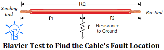
Ground fault of a single cable can be located using Blavier’s test. In this kind of test, low voltage supply, an ammeter and voltmeter are used in a bridge network. Resistance between one end of the cable (Sending End) and earth is measured while “Far End” is isolated from the earth.
Suppose we know the total resistance of a single core cable (before the fault) which is RΩ. And;
Fault to ground resistance = r
Resistance from the Far end to the cable fault = r1
Resistance from the testing end of the cable to the fault = r2
 Now, we will connect and then disconnect the earth connection from the far end of the cable to measure two resistances. These measurements can be done by a LT (Low tension) supply and a bridge network.
First of all, We will insulate the far end of the cable to determine the resistance between line to ground which is;
R1 = r2 + r ………………………. (1)
Now, we will ground or earth the far end of the cable to find the resistance between line to ground again.
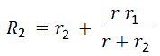 But the total resistance (before occurring the fault) was
R = r1 + r2 ……………………….. (3)
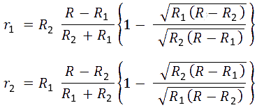
Solving the above equations for r2 (fault location or distance), we get
![]()
The value of x = r2 is generally less than the value of R2. Therefore, we consider (-) instead of (±) in the above equation.
![]()
Loop Tests to finding Cable faults
These kinds of tests are carried out on short circuit faults or earth fault in underground cables. Cable faults can be easily located if a sound cable runs along with the grounded cables. Following are the types of loop tests.
- Murray loop Test
- Varley loop Test.
- Earth Overlap Test
2. Murray Loop Test
The connection on how a cable faults can be located using Murray loop test method is shown below.
Wheatstone bridge’s principle is used in murray loop test to find the cable faults. Ra and Rb are the two ratio arms consisting of resistors. G is a galvanometer. The cable having fault (Rx) is connected to the second cable (Sound cable Rc) through low resistance link at the far end. The Wheatstone bridge is kept in balance by adjusting resistance of the ratio arms Ra and Rb until the galvanometer deflection is zero.
Thus…

Solving for x, we get;
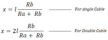 where
where
l = length of a single cable (In meters of yards)
2l = total length of two cables
x = distance from the upper side to the fault
3. Varley Loop Test
The only difference between Murray loop test and Varley loop test is that Varley loop test provision is made for measurement of total loop resistance instead obtaining it from the relation

In this test, the ratio arms Ra and Rb are fixed and balance position is obtained by varying the known variable resistance (Rheostat).
As we have explained the equation in above section of murray loop test… the story is same for varley test as well…
For earth Fault or short circuit fault in the cables, the switch key is first thrown to position 1, the variable resistance S is varied till the bridge is balanced for resistance value of S1. So,
When key is on Position 1

When key is on Position 2
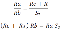 From equation 1 and 2, we get,
 Since the value of Ra, Rb, S1 and S2 are known, the value of Rx can be determined then by
Loop Resistance =
 If “r” is the resistance of the cable per meter length, then, distance of the cable fault from the test end is
 4. Earth Overlap Test
In earth overlap test, two measurements are performed (instead of one as in Blavier test). The first measurement of resistance is R1 (between Line to ground i.e. from the testing end to the far (earthed) end).
The second measurement of resistance is R2 (between Line to ground i.e from the far end and the testing (earthed) end).
Both measurements are equal as follows:

As in the Blavier test, we also suppose that we know the actual resistance of the cable before the cable fault which is R.
R = r1+r2
 5. Open Circuit Test
Open circuit fault can be occurs when cable is pulled out of its joint or a break occurs in the cable. Such a fault can be traced by carrying out capacity test. The capacitance of the faulty cable is measured from both ends of the cable either by means of ballistic galvanometer or by bridge method. Capacitance of the cable to the ground is proportional to the length of the cable.
6. Potential Fall Test
In Potential fall test, Ammeter, voltmeter, Variable resistor (rheostat) and battery are connected as shown below to find the fault location in the cable. This test is carried out with the help of a sound cable that has no fault running along the faulty cable as shown below The fault point distance can be given as:
 Where
Where
- V1 and V2 = the voltmeter readings at point A and B;
- L = length of the faulty core
- X = length of core between fault and testing end A.
Related Posts:
- Insulation Resistance of a Cable | Why Cables are insulated?
- Why Power Transmission Cables & Lines are Loose on Electric Poles & Transmission Towers?
- Why Coaxial Cables are Highly Insulated?
- Ferrite Bead: Tiny Cylinder in Power Cords & Cable. Why?
- Electrical Wire & Cable Size Calculator (Copper & Aluminum)
- Wire & Cable Size Calculator in AWG
- How to Find The Suitable Size of Cable & Wire for Electrical Wiring Installation.


Cable Faults, Types, Causes and How to locate faults in Cables via different Tests.
Can you send me as attachment via e-mail, as I cannot save or print the whole content.
At the top right corner (sidebar) submit your email and click subscribe… You will get each post in the email then… Thanks
I’m Johnson Oyewole am an Electrical Engineer,i want to learn more
Great overview of cable faults and how to find them. This is something good for beginners and for experienced electricians who are needing a refresher on things! Thanks for sharing this.
A good effort for clear understanding of cable faults
Dear,
r1 and r2 positions are wrong, they should be swapped with each other.
our 11kv cable y phase earth fault dc voltage drop test carried out .forward direction feed 2.14 vdc and measured 0.13v and 2.01v. After feed the reverse polarity supply 2.14v and measured 1.01v and 1.14v .length cable 2L=3400m.Please calculate the fault distance.