Voltage Divider Rule (VDR) – Solved Examples for R, L and C Circuits
Voltage Division “VDR” for for Resistive, Inductive and Capacitive Circuits
What is Voltage Divider Rule?
In a circuit, when a number of elements are connected in series, input voltage divides across the elements. And in a circuit, when a number of elements are connected in parallel, the current divides across the elements.
Therefore, in a parallel circuit, the current divider rule is used and in a series circuit, the voltage divider rule is used to analyze and solve the circuit.
When two or more impedances are connected in series, the input voltage is divided into all impedances. To calculate the voltage across each element, the voltage divider rule is used. The voltage divider rule is the most important and simple rule in circuit analysis to calculate the individual voltage of any elements.
The voltage divider rule is also known as the potential divider rule. In some conditions, we require specific output voltage. But we don’t have that specific value of the source. In this condition, we make a series of passive elements and reduce the voltage level to a specific value. And here, the voltage divider rule is used to calculate the specific output voltage.
According to elements used in the circuit, the voltage divider rule can be classified into three types; resistive voltage divider, inductive voltage divider, and capacitive voltage divider. Now, we will prove the voltage divider rule for all these types of circuits.
Related Post:
- Voltage Divider “VDR” Calculator, Examples & Applications
- Voltage & Current Divider Rules (VDR & CDR) Equations
Voltage Divider Rule for Resistive Circuits
To understand the resistive voltage divider rule, we take a circuit having two resistors are connected in series with the voltage source.
As the resistors are connected in series, the current that passes through both resistors is the same. But the voltage is not the same for both resisters. The input voltage of the circuit divides into both resisters. And the value of individual voltage depends on the resistance.
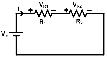
As shown in the above figure, two resistors R1 and R2 are connected in series with the voltage source Vs. The total current supplied by the source is I ampere. As all elements are connected in series, it will make a single loop and the current that passes through all elements is the same (I amp).
The voltage across resistor R1 is VR1 and the voltage across resistor R2 is VR2. And the total supplied voltage divides between both resisters. Hence, the total voltage is a sum of VR1 and VR2.
VS = VR1 + VR2 … (1)
According to Ohm’s law,
VR1 = IR1 + IR2 … (2)
Therefore, from the equation-(1) and (2);
VS = IR1 + IR2
VS = I(R1 + R2)

Now, put the value of current I in the equation-(2);
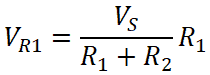
VR1 = IR1
Similarly;
VR2 = IR2

Hence, the voltage divider rule for a resistive circuit is opposite to the current divider rule. Here, the voltage of the resistor is a ratio of multiplication of total voltage and that resistance to the total resistance.
Related Posts:
- Thevenin’s Theorem. Step by Step Guide with Solved Example
- Norton’s Theorem. Step by Step Guide with Solved Example
Solved Example of Resistive Circuit using VDR
Example-1
Find the voltage across each resistor using the voltage divider rule.
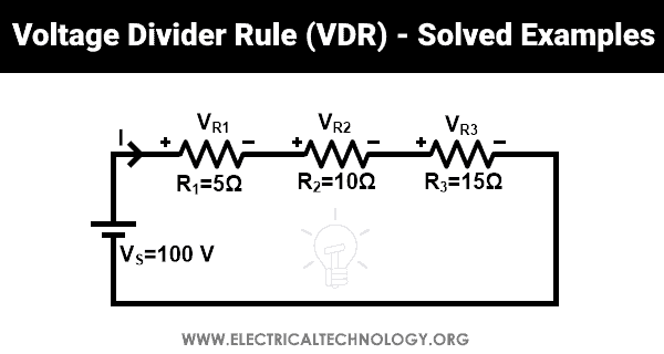
Here, three resistors (R1, R2, and R3) are connected in series with 100V source voltage. The voltage across resistors R1, R2, and R3 are VR1, VR2, and VR3 respectively.
The voltage across resistor R1;
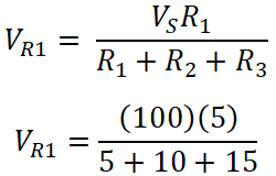
VR3 = 500 / 30
VR3 = 16.67 V
The voltage across resistor R2;
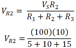
VR3 = 100 / 30
VR3 = 33.33 V
The voltage across resistor R3;
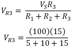
VR3 = 1500 / 30
VR3 = 50 V
Total voltage VT;
VT =VR1 + VR2 + VR3
VT = 16.67 + 33.33 + 50
VT = 100 V
VT = VS
Hence, it is proved that the total voltage= is similar to the supplied voltage.
Related Posts:
- Superposition Theorem – Circuit Analysis with Solved Example
- Maximum Power Transfer Theorem for AC & DC Circuits
Voltage Divider Rule for Inductive Circuits
When a circuit having more than two inductors is connected in series, the current that passes through the inductors is the same. But the source voltage is divided into all inductors. In this condition, the voltage across the individual inductor can be found by the inductor voltage divider rule.
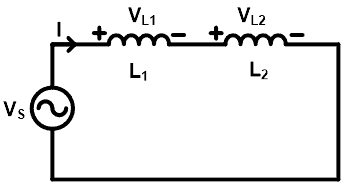
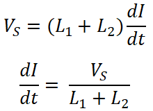
Consider as shown in the above figure, two inductors (L1 and L2) are connected in series. And total current I pass through the inductor. The voltage across inductor L1 is VL1 and the voltage across inductor L2 is VL2. And the supply voltage is VS. Now, we need to find the voltage VL1 and VL2 using the inductor voltage divider rule.
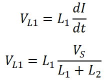
As we know the equation of voltage for inductor;

Where Leq is the total inductance of the circuit. Here, two inductors are connected in series. Therefore, the equivalent inductance is a sum of both inductances.
Leq = L1 + L2
From, equation-(3);
Now, the voltage across inductor L1 is;
Similarly, the voltage across inductor L2 is;
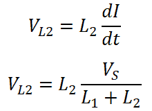
So, we can say that the voltage divider rule for an inductor is the same as the resistors.
Related Posts:
- Millman’s Theorem – Analyzing AC & DC Circuits – Examples
- Tellegen’s Theorem – Solved Examples & MATLAB Simulation
Solved Example of Inductive Circuit using VDR
Example-2
Find the voltage across each inductor for the given circuit using the voltage divider rule.
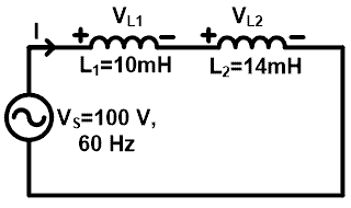
Here, two inductors are connected in series with 100V, 60Hz source. The voltage across inductor L1 is VL1 and the voltage across inductor L2 is VL2.
To find the voltage across inductors, we need to find the reactive impedance of each inductor.
The reactive impedance across inductor L1 is;
XL1 = 2 π f L1
XL1 = 2 × 3.1415 × 60 x 10 × 10-3
XL1 = 3.769 Ω
The reactive impedance across inductor L2 is;
XL2 = 2 π f L2
XL2 = 2 × 3.1415 × 60 x 14 × 10-3
XL2 = 5.277 Ω
According to the voltage divider rule,
The voltage across inductor L1 is;

VL1 = 41.66 V
The voltage across inductor L2 is;

VL2 = 58.35 V
Total voltage VT is;
VT =VL1 + VL2
VT = 41.66 + 58.35
VT = 100 V
VT = VS
So, the total voltage is the same as supplied voltage.
Related Posts:
- Compensation Theorem – Proof, Explanation and Solved Examples
- Substitution Theorem – Step by Step Guide with Solved Example
Voltage Divider Rule for Capacitive Circuits
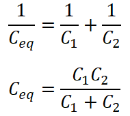
In a capacitor, the voltage divider rule is different compare to the inductor and resistor. To calculate the voltage divider rule for capacitors, let’s consider a circuit having two or more capacitors connected in series.

Here, two capacitors are connected in series with the source voltage VS. The source voltage divides into two voltages; one voltage is across the capacitor C1 and a second voltage is across the capacitor C2.
The voltage across capacitor C1 is VC1 and the voltage across capacitor C2 is VC2. As shown in the above circuit diagram, both capacitors are connected in series. Therefore, the equivalent capacitance is;
The total charge delivered by the source is Q;
Q = Ceq VS

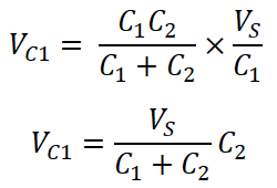
The voltage across capacitor C1 is;
VC1 = Q1 / C1
The voltage across capacitor C2 is;
VC2 = Q1 / C2
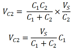
So, from the calculation, we can say that the individual voltage across the capacitor is a ratio of multiplication of total source voltage and opposite capacitance to the total capacitance.
Related Posts:
- Current Divider Rule (CDR) – Solved Examples for AC and DC Circuits
- Current Divider Rule Calculator – CDR Formula & Calculations
Solved Example of Capacitive Circuit using VDR
Example-3
Find the voltage across each capacitor for a given network using the voltage divider rule.
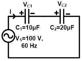
Here, two capacitors are connected in series with 100 V, 60 Hz source. The voltage across capacitor C1 is VC1 and the voltage across capacitor C2 is VC2.
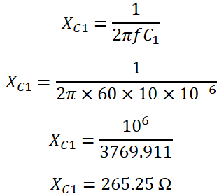
To calculate the voltage across each capacitor, we need to find the capacitive impedance.
The capacitive impedance across C1 is;
The capacitive impedance across C2 is;
XC2 = 1 / (2 π f C2)
XC2 = 1 / (2 π × 60 × 20 ×10-6)
XC2 = 10-6 / 7539.822
XC2 = 132.63 Ω
According to the voltage divider rule, the voltage across capacitor C1 is;
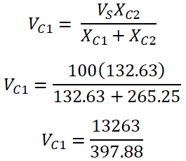
VC1 = 33.33 V
the voltage across capacitor C2 is;
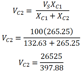
VC2 = 66.67 V
The total voltage across capacitor VT is;
VT =VC1 + VC2
VT = 33.33 + 66.67
VT = 100 V
VT = VS
Related Electric Circuit Analysis Tutorials:
- SUPERNODE Circuit Analysis – Step by Step with Solved Example
- SUPERMESH Circuit Analysis – Step by Step with Solved Example
- Voltage Divider Rule “VDR” Calculator – Examples & Applications
- Current Divider Rule “CDR” Calculator – Examples & Applications
- Kirchhoff’s Current & Voltage Law (KCL & KVL) | Solved Example
- Cramer’s Rule Calculator – 2 and 3 Equations System for Electric Circuits
- Wheatstone Bridge – Circuit, Working, Derivation and Applications
- Electrical and Electronics Engineering Calculators
- 5000+ Electrical and Electronic Engineering Formulas & Equations


