Analog to Digital Converter (ADC) – Block Diagram, Factors & Applications
What is Analog To Digital Converter (ADC)? Block Diagram, Factors & Applications Of ADC
What is ADC (Analog To Digital Converter)?
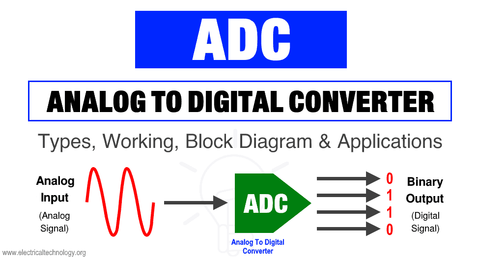
ADC stands for analog to digital converter. It is an electronic device used for converting an analog signal into a digital signal.
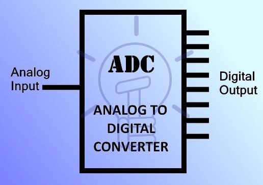
The analog input signal of ADC is continuous time & continuous amplitude signal. The output of ADC is a discrete time and discrete amplitude digital signal.
Why ADC?
In the real world, every real quantity such as voice, temperature, weight etc exists in the analog state. And it cannot be processed by any digital device such as a computer or a cell phone.
These analog quantities are converted into digital form so that a digital device can process it. This conversion is done using analog to digital converter.
Block Diagram of ADC
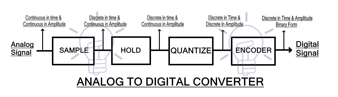
The analog signal is first applied to the ‘sample‘ block where it is sampled at a specific sampling frequency. The sample amplitude value is maintained and held in the ‘hold‘ block. It is an analog value. The hold sample is quantized into discrete value by the ‘quantize‘ block. At last, the ‘encoder‘ converts the discrete amplitude into a binary number.
Analog To Digital Conversion Steps
The conversion from analog signal to a digital signal in an analog to digital converter is explained below using the block diagram given above.
Sample
The sample block function is to sample the input analog signal at a specific time interval. The samples are taken in continuous amplitude & possess real value but they are discrete with respect to time.
The sampling frequency plays important role in the conversion. So it is maintained at a specific rate. The sampling rate is set according to the requirement of the system.
Hold
The second block used in ADC is the ‘Hold’ block. It has no function. It only holds the sample amplitude until the next sample is taken. The hold value remains unchanged till the next sample.
Quantize
This block is used for quantization. It converts the analog or continuous amplitude into discrete amplitude.
The on hold continuous amplitude value in hold block goes through ‘quantize’ block & becomes discrete in amplitude. The signal is now in digital form as it has discrete time & discrete amplitude.
Encoder
The encoder block converts the digital signal into binary form i.e. into bits.
As we know that the digital devices operate on binary signals so it is necessary to convert the digital signal into the binary form using the Encoder.
This is the whole process of converting an Analog signal into digital form using an Analog to Digital Converter. This whole conversion occurs in a microsecond.
Factors Of ADC
Resolution:
Resolution of an ADC is the number of bits that represents the digital signal’s amplitude.
The analog signal has continuous amplitude. It can have infinite values i.e. real, floating basically any value one can imagine. On the other hand, the digital signal has a discrete and finite number of values. These discrete values are represented using binary numbers (bits).
To better understand the idea of resolution of ADC,
-
1-Bit Resolution
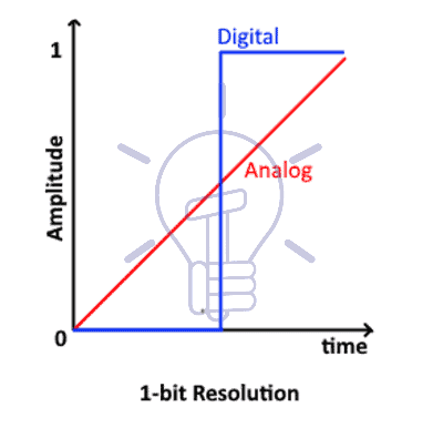
The figure above shows an analog signal represented in a digital form which is either 0 or 1. This is a 1-bit resolution. The resolution of ADC defines its number of steps.
number of steps = 2n
Where n is the number of bits. Therefore, there are 2 steps in 1-bit resolution.
-
2-Bit Resolution
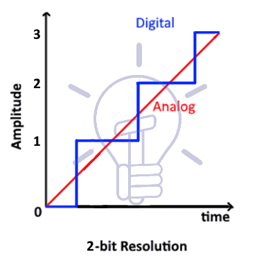
This figure shows the conversion of analog to digital in 2-bit resolution. There are 4 steps or quantization levels.
No of steps = 2n = 22 = 4
-
4-Bit Resolution

This figure shows 4-bit resolution. The number of steps in 4-bit resolution is 16.
No of steps = 2n = 24 = 16
The number of steps increases exponentially with increase in the bit-resolution. It also implies that by increasing the bits of resolution the converted digital signal becomes more like the original analog signal. So ideally, we can say that a digital signal with infinite resolution is an analog signal.
Related Post: Introduction to Signals, Types, Properties, Operation & Application
Width Of The Step
The voltage difference between two adjacent steps is known as the width of the step. It is denoted by Δv.
So a single step represents a fixed voltage that is
Δv = vref/2n
Where vref is the maximum voltage being converted & n represents the bits of resolution.
For example:
vref = 10.24v & n = 10 bits
Then:
Δv = 10.24/210
Δv = 10.24/1024
Δv = 0.01v
Thus the step-size or width of the step is 0.01v. In this ADC, a single bit increase represents a 0.01v of increase in the analog input. If analog input is increased by 0.01v then the output is increased by 1 bit.
Quantization Error
The ADC updates its value if the increase or decrease in its input voltage is greater than Δv/2. Any change less than Δv/2 will not be registered. This is known as Quantization Error.
In other words, the difference between the input and the digital round-off figure of output is known as quantization error.
The increase in the resolution of the ADC decreases the step-size if the vref remain constant. Consequently, the quantization error decreases.
Sampling Rate
The number of samples taken during a single second is known as sampling rate or sampling frequency.
The sampling rate should be set according to the input signal. It should not be very low or very high.
Example of sampling:
This example shows that the sampling rate is 0.5 sec, as it takes 2 samples in one second.
Aliasing

If the sampling rate is very low then the resultant signal will not look anything like the original signal. In fact, it will become a different signal after reconstruction. This problem is known as aliasing.
To avoid this problem, the sampling rate should be kept higher than twice the frequency of the input signal. Anti-aliasing filters are also used for removing the frequency components higher than one half of the sampling rate. it blocks the aliasing components from being sampled.
Nyquist Criteria
Nyquist criteria suggest the minimum possible sampling rate for an analog signal which can be reconstructed successfully. If the highest frequency of the analog signal is f, the signal can be reconstructed successfully from its samples, if the samples are taken at a sampling frequency greater than 2f.
Offset
The offset in ADC is the shift in the digital output. For example, for input vin = 0, the output might not necessarily be digital 0. It can be digital 5, which will be the offset of the ADC.
Related Post: What is Quantization & Sampling? Types & Laws of Compression
Application of ADC
In the modern world of growing technology, we are dependent on digital devices. These digital devices operate on the digital signal. But not every quantity is in digital form instead they are in analog form. So an ADC is used for converting analog signals into digital signals. The applications of ADC are limitless. Some of these applications given below:
- Cell phones operate on the digital voice signal. Originally the voice is in analog form, which is converted through ADC before feeding to the cell phone transmitter.
- Images and videos captured using camera is stored in any digital device, is also converted into digital form using ADC.
- Medical Imaging like x-ray & MRI also uses ADC to convert images into Digital form before modification. They are then modified for better understanding.
- Music from the cassette is also converted into the digital form such as CDs and thumb drives using ADC converters.
- Digital Oscilloscope also contains ADC for converting Analog signal into a digital signal for display purposes & different other features.
- Air conditioner contains temperature sensors for maintaining the room temperature. This temperature is converted into digital form using ADC so that onboard controller can read & adjust the cooling effect.
In today’s modern world almost every device has become the digital version of itself & they need to have ADC in it. Because it has to operate in digital domain which can be only acquired using analog to digital converter (ADC).
Related Posts: