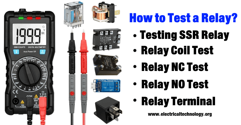
How to Test a Relay? Checking SSR & Coil Relays
How To Test A Relay Using Multimeter & Battery? Its Terminal Identification & Operation
In this article, we will show you “how to test a relay“. A relay usually gets damaged due to a number of reasons. So it is crucial to test a relay if it stopped working before you replace it or throw it away. To test a relay, you need to have a multimeter or an ohmmeter.
Before testing any relay you need to know about the relay itself.
What is a Relay?
A relay is an electromechanical switch. It controls a circuit using a very low current that energizes the coil. The coil generates a magnetic field which attracts a movable lever (pole) to change the switch position.
Terminals Of Relay
In general SPDT (Single pole double throw) type of relay, there are Five terminals.

- Two of them are coil input terminals, which is basically the control input (activates & deactivates the relay)
- The common terminal is the feeding input of the high voltage circuit. This input is passed through the pole (switch) of the relay to either NO terminal or NC terminal.
- Normally opened (NO) terminal is that terminal of the relay whose connection with common terminal remains open when the relay is deactivated. It closes when the relay activates.
- Normally closed (NC) terminal is the other terminal of relay whose connection with common terminal remains closed until the relay activates.
Related Post: How to Test a Diode using Digital & Analog Multimeter?
Terminal Identification
Usually, the terminals are specified on the protective cover of the relay. if there is no information about its terminals then you can identify it using an Ohmmeter.

- The coil has a resistance of fewer than 400 ohms except for some cases. so the terminals having resistance around 300 ohms will be the coil terminals.
- The NC terminal has almost 0-ohm resistance with respect to the common terminal when the relay is deactivated.
- The NO terminal has infinite resistance with respect to the common terminal when the relay is deactivated.
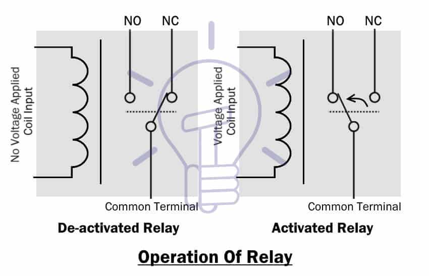
Operation Of Relay
Deactivated mode: When there is no power source connected to the coil input, the current will flow through the Common terminal to NC terminal.
Activated mode: when the coil is energized, the current will only flow from common terminal to NO terminal.
Relay Coil Test:
This test is performed to examine the coil condition (open or closed or shorted turns). This problem occurs due to exceeding the input voltage of the coil. The operating input parameter’s min & max limits are specified in its datasheet.
- Related Post: How to Test a Capacitor by Digital & Analog Multimeter ?
Using Multimeter
There are two modes in multimeter which can be used to test a relay.
Continuity Test Mode
The main purpose of this test is to check the continuity of the coil.
- Set the multimeter in continuity test mode.
- Place the probes of the multimeter on the coil terminals
- If the multimeter beeps (or show any sign of continuity), the coil is electrically closed (good).
- If the multimeter does not beep, the coil is open & damaged. The relay needs to be replaced.
If your meter does not have a continuity function or for some reason does not show any sign of continuity then use the second method.
Unfortunately, if you test a relay using this continuity method it will not reveal any turns of the coil that has been shorted.
Resistance Mode
If you choose to test a relay using Ohmmeter, you need to do a tad bit of research beforehand. You need to know about the nominal value of the coil resistance from its datasheet. You can find its datasheet online by using the model number usually written on its protective case.
However, most of the time the resistance of the coil lies beneath 400 ohms.
- Set the multimeter in Ohmmeter.
- Place the probes on both terminals of the coil.
- Record the resistance shown in the multimeter.
If the measured resistance matches the resistance mentioned in its datasheet, the relay coil is fine.
If the resistance is very low or very high, the coil most likely has short turns or opened respectively.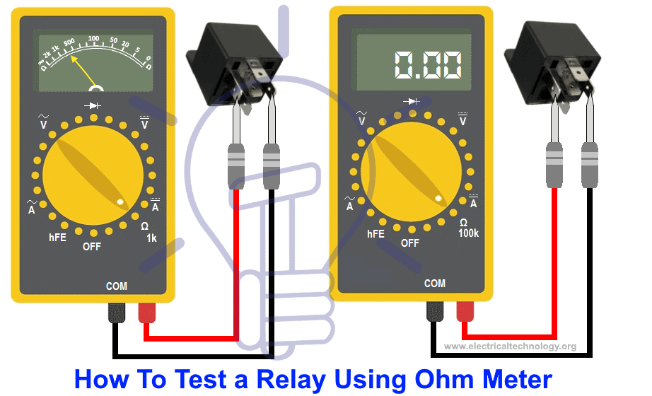
Related Post: How to Check a Transistor by Multimeter (DMM+AVO) ? – NPN & PNP
Using Power Source (Battery)
Remember, do not use this method unless you have got the technical skills of using a power source taking the necessary safety precautions.
- Remove the relay if it is in any circuit.
- Identify the coil terminals.
- Connect the battery with the coil terminals.
- Listen, if you hear a click sound as soon as you connect the coil terminals, the relay works
- If it does not click, that means the coil is open & damaged. The relay needs to be replaced because the coil cannot be repaired.
NC (Normally Closed) Terminal Test:
This relay test provides the necessary information regarding the switching of the relay to ensure that the terminals do connect & disconnect during the coil energizing.
The NC terminal remains closed until the relay activates.
- Set the Multimeter in continuity mode.
- Place one probe on NC terminal and the other probe on common terminal of the relay.
- While the coil is de-energized (deactivated), the meter ought to show continuity indication (beep).
- Now activate the coil by using power source or you could just manually push the lever (armature) by pushing the test button (if it has) or using your finger.
- The meter should stop the continuity indication (beep)
If the meter does not beep at all, it is probably the conductors inside are broken.
You can also check it using an Ohmmeter. A good relay has NC terminal resistance of 0 Ohm when deactivated & infinite resistance when activated.
NO (Normally Open) Terminal Test:
This test ensures the connectivity between the common terminal & the NO (normally open) terminal.
NO terminal remains open until the relay activates.
- Set multimeter in continuity test mode.
- Place the probes on NO terminal & common terminal.
- The meter will not beep or show any sign of continuity when the relay is deactivated.
- Now activate the relay or touch the contacts manually, the meter should beep as a sign of continuity.
If the meter does not show any sign of continuity, the relay conductors are damaged.
Related post: How to find The value of Burnt Resistor ( By three handy Methods )
How to Test a Solid State (SSR) Relay ?
Testing DC Controlled SSR Relay
This is the easiest and accurate way to check and troubleshoot an SSR (Solid State Relay). To test a solid state relay, follow figure and steps given below.
- Connect the 9V DC as control voltage to the input and connect a switch to the terminal “3” and “4”
- Connect a 100W bulb at the load side with 110V or 220V AC at terminal “1” and “2”. The first terminal “1” of Relay should be connected to the bulb and AC voltage while the second wire from outlet will be connected to terminal “2” to complete the circuit as shown in fig below.
- Now, Switch ON and OFF the “ON/OFF Switch”. If the light bulb turn ON and OFF respectively, Relay is in good condition otherwise, relay is damaged and you need to replaced with new one.
Testing AC Controlled SSR Relay
The operation is same as above while testing AC Controlled solid State Relay. But you will have to provide AC Control Voltage instead of DC as shown in fig below.
According to the schematic given below, If light bulb ON when you close the switch and “OFF” again by opening the switch. The relay is good as expected otherwise, relay is faulty and you should change with new one.
Related Post: How to Find the value of SMD Resistors
Testing Solid State Relay in Diode Test Mode (DMM)
To test a solid state relay by using digital multimeter, follow the steps given below:
- Rotate the multimeter knob to the “Diode Test Mode” as shown in fig below.
- Connect the A1(+) and A2(-) terminals to the multimeter according to the schematic.
- If the relay is in good condition, multimeter will show 0.7 (In case of silicon transistor) or 0.3 (in case of germanium transistor)
- If multimter shows “0” or “OL”, its mean that the relay is damaged and faulty.

These are some of the basic & easy methods to test a relay. If you are using another method or know special way to check and troubleshoot a relay, let’s know in the comment box below to share with our audience.
Related Posts:


many thanks.
very helpful