How to Wire 8-PIN Relay for Holding or Latching Circuit?
Wiring of Latching / Holding Circuit using 8-Pins PLA Relay
Relays are essential components in electronic and electrical systems that enable the control of high-power circuits through low-power control signals. One common application of relays is to create a holding circuit, which maintains the state of a circuit even after the control signal is removed. In this article, we will delve into the concept of a holding circuit using an 8-pin relay, its working principle, components, and practical considerations.
What is an 8-PIN Relay?
An 8-pin relay (also known as 2C/O Relay i.e. 2 commons and outputs) is an electromechanical or solid-state device that serves as a switch to control large electrical circuits using a low-power control signal. It typically has eight pins or terminals that facilitate its operation and connection within a larger electrical system. The fundamental components of an 8-pin relay include a coil, normally open (NO) contacts, and normally closed (NC) contacts.
Related Posts:
- ON / OFF 3- Phase Motor Using 8-PIN Relay and DOL Starter
- Automatic ON/OFF Circuit Using Two 8-PIN Timers for 1 & 3-Φ Load
Construction:
Here’s a breakdown of the components and their functions:
- Coil: The coil is an electromagnetic winding that generates a magnetic field when a voltage is applied to it terminals (2 & 7). When the coil is energized, the magnetic field causes a movable armature or relay switch to be attracted towards it.
- Normally Open (NO) Contacts: These are switch contacts (3 & 6) that are normally open (disconnected) when the relay is in its resting state or not energized. When the coil is energized, the armature moves to close the NO contacts, allowing current to flow through the circuit.
- Normally Closed (NC) Contacts: These contacts (4 & 5) are normally closed (connected) when the relay is in its resting state. When the coil is energized, the armature moves to open the NC contacts, interrupting the current flow through the circuit.
Connections of 8-Pin Relay Terminals:
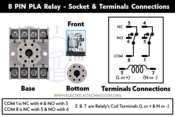
As shown in fig, the 8-pin relay terminals are interconnected with the following pin configuration:
- Pins 2, 7: Relay’s Coil Connections ( L or + and N or – = energizing the coil)
- Pin Common (COM) 1 is normally closed (NC) with 4 and Normally Open (NO) with 3.
- Pin Common (COM) 8 is normally closed (NC) with 5 and Normally Open (NO) with 6.
Working Principle of an 8-Pin Relay
An 8-pin relay consists of a coil, a set of normally open (NO) contacts, and a set of normally closed (NC) contacts. The coil is energized by applying a voltage across its terminals, which generates a magnetic field that attracts a movable armature. This action causes the contacts to switch from their normal positions.
When the coil is de-energized, the armature returns to its initial position due to spring action, and the contacts revert to their normal states. This fundamental behavior of relays forms the basis for creating holding circuits.
How to Wire an 8 PIN Relay?
In the following wiring diagram, two light bulbs are controlled using an 8-pin relay, where both bulbs will either glow or turn off simultaneously during relay operation. For instance, when the relay labeled CB is in the OFF state, both light bulbs will be off since they are connected to the NO (Normally Open) contacts of the relay. Conversely, when the relay is turned ON, both light bulbs will illuminate.

Different wiring configurations and controls can be employed according to the circuit’s requirements. For instance, if you want to switch ON the RED bulb while turning OFF the BLUE bulb, simply connect the Blue light bulb to the 5th terminal (NC – Normally Closed) of the relay, instead of the 6th terminal (NO – Normally Open).
In this setup, when the relay is ON due to the activation of the MCB (Miniature Circuit Breaker), the NO contact of the relay will become NC, and vice versa. As a result, the Red bulb will illuminate while the Blue bulb will be turned off. This process will reverse when the relay is turned OFF—meaning the Red bulb will turn off while the Blue bulb will start glowing.
What is a Holding Circuit?
Holding circuits, also known as latch circuits, are designed to maintain the current state of a circuit after the control signal is removed. This functionality is particularly useful in situations where consistent circuit states are required, such as in safety systems or power distribution networks.
Holding or Latching Circuit Using 8-PIN PLA Relay
Components Required
- 8-Pin Relay
- Power Supply
- Switch/Button
- Load (e.g., Lamp or Motor)
Circuit Diagram
Below is the step-by-step guide to wire a latching or holding circuit using 8-pin relay according to the given circuit diagram.
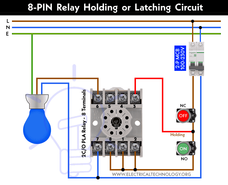
- Connect the phase wire from the two-poles MCB (100-230V AC breaker) to the 2, 1 & 8 terminals of the relay.
- Similarly, wire the neutral wire from the MCB to the 7 terminal of the relay.
- Connect two pushbuttons (NC and NO) in series with the phase wire from the CB to the relay’s terminals 2,1 & 8.
- Connect a jumper wire from the phase (from MCB) to the 11 and 6 terminals of the relay.
- Connect a jumper as holding wire from the 2nd terminal of NC (or starting terminal of NO pushbutton) to the 3 terminal of the relay.
- Finally, connect the output wire from terminals 6 of the relays to light bulb.
- Lastly, connect the neutral and ground/earth wire to both light bulb holders. The circuit is complete.
Operation of Holding Circuits
When the coil is energized by the control signal by pressing the GREEN NO pushbutton, it causes the NO contact to close, completing the circuit to the load. Once the coil is energized, even if the control signal is removed (by releasing the Green NO push button), the NO contact remains closed due to the mechanical latching action of the relay (as the terminal # 3 is directly connected to the phase supply). This keeps the load powered and the circuit closed. The NC contact is simultaneously opened, ensuring that the load is not connected to the negative terminal.
To reset the circuit, the control signal is applied again by pressing the RED NC pushbutton, which de-energizes the coil. This opens the NO contact and closes the NC contact, turning off the load.
Practical Applications
Holding circuits find applications in various domains, including industrial automation, safety systems, automotive electronics, and home appliances. For example, a holding circuit can be used to maintain the state of a motor even after releasing the button that initially started it.
Generally, Holding circuits are employed in various applications for different purposes, including:
- Safety Systems: Holding circuits can be used in safety systems to ensure that a critical operation, such as an emergency stop, remains active even if the initiating button or signal is released. This prevents unintended restarts and maintains the safe state of the system.
- Latch Control: In applications where you want to control a device using a single button or signal (like a toggle switch), a holding circuit can be used to keep the device in the desired state until the signal is given to switch it off.
- Power Distribution: Holding circuits can be used in power distribution systems to maintain the state of a breaker or switch, even if the control signal is removed. This can be useful in situations where consistent power supply or isolation is required.
- Remote Control: Holding circuits are also used in remote control systems, where a signal from a remote location can control a device’s state and keep it that way until another signal is sent to change it.
- Industrial Automation: In automation systems, holding circuits can be used to maintain the state of motors, actuators, and other devices after they have been triggered by a control signal.
Advantages and Disadvantages
Advantages:
- Reliable maintenance of circuit states.
- Minimal energy consumption in the holding state.
- Suitable for applications requiring a specific state until manually reset.
Disadvantages:
- Can be more complex compared to simple control circuits.
- May require additional components for control and protection.
Safety Considerations
When designing and working with holding circuits, it’s important to consider safety measures, such as using appropriate voltage levels, incorporating overload protection, and ensuring proper insulation to prevent electrical hazards.
Related Posts:
- How to Wire 11-PIN Relay for Interlocking and Holding Circuits?
- How to Wire 14-PIN Relay for Holding or Latching Circuit?
- ON / OFF 3- Phase Motor Using 11-PIN Relay and DOL Starter
- ON / OFF 3- Phase Motor Using 14-PIN Relay and DOL Starter
- How to Control a Three-Phase Motor Using Solid-State Relay?
- Sequential Motor Control Circuit Using ZEN Programable Relay


How to auto operate for STP air blower on every 2 hours once