ON / OFF 3-Phase Motor Using 14-PIN Relay and DOL Starter
How to Start and Stop a Three-Phase Motor using 14-PIN PLA Relay and DOL Starter?
Controlling a 3-phase motor using a DOL starter is the simplest method among others, such as star-delta starters, VFD starters, relay starters, and PLC-based starters, etc. In the following motor control guide, we will discuss how to control the ON and OFF operation of a three-phase motor using a 14-PIN relay and DOL starter, along with wiring, power, and control circuit diagrams.
A A (DOL) Direct-On-Line starter is a simple motor starter consisting of a contactor and overload relay. we have used 14-terminal PLA relay to control the DOL starter and motor. A 14-PIN relay is an electromechanical device designed to control complex functions within a circuit. In this setup, the 14-PIN relay serves as the interface between the control circuit and the DOL starter, enabling remote or automated control over the motor’s operation.
Components Needed
To make a simple ON and OFF control circuit for a 3-phase motor using a 14-PIN relay and a DOL starter, the following components are required:
- Three-Phase Motor
- 14-PIN PLA Relay
- DOL Starter (based on Contactor & Thermal Overload Relay)
- 2P-MCB and 3-P MCCB
- Control Switches (Start “NO” and Stop “NC”)
- 3 NO of polit light indictors
- Single Phase & Three Phase Supply
- Wires & Cables
Wiring the Power and Control Circuit
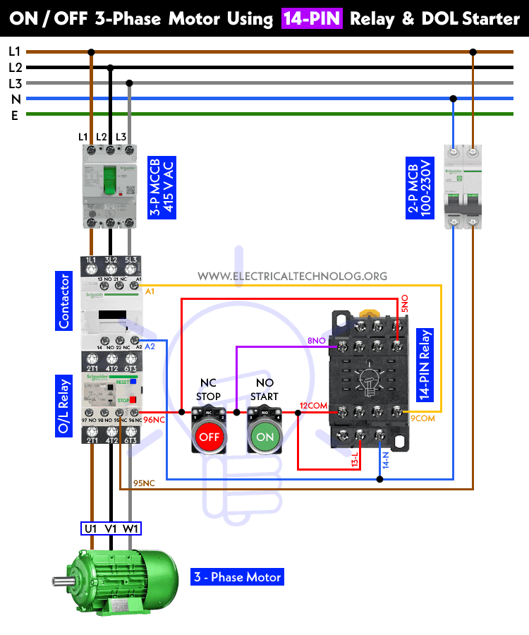
According to the following wiring, power and control diagram, follow the given basic steps to wire the circuit for controlling the ON/OFF operation of a three-phase motor using an 14-PIN relay and a DOL starter.
-
- Connect the three-phase power supply of 415V AC from the 3-P MCCB to the L1, L2, and L3 terminals of the Contactor, O/L relay (T1, T2, T3) , and then the 3-Phase motor (U1, V1 & W1) respectively (wiring power circuit).
- Connect the Phase (Line) wire from 2P-MCB to the 95-NC terminal of the O/L relay
- Connect two push-buttons in series (RED-NC to Stop and Green-NO to Start) from the 96-NC terminal of the O/L relay. Now, connect the output terminal of the NO-push-button (Green) to the 12-COM and 13-L terminals of the 14-PIN relay (as shown in control diagram).
- Connect a jumper wire for holding from the output of the Red-NC (Stop) push button (or the starting point of the Green-NO push-button) to the 8-NO terminal of the PLA relay.
- Wire the 5-NO terminal of the PLA relay to the 1st (starting) terminal of Red (NC) pushbutton.
- Now, wire the A1 terminal of contactor to the 9-COM terminal of 14-Pins Relay.
- Connect the neutral wire from the MCB to the A2 terminal of the contactor and 14 terminal of the 14-PIN relay.
- Finally, properly ground the motor, DOL starter, and control circuit to ensure safety.
Working of Starting & Stopping 3-Phase Motor using 14-PIN Relay & Contactor
- Pressing the start button energizes the relay’s coil, which activates the DOL starter’s contactor.
- This is because, the NC becomes NO and vice versa. But the holding wire (to 8-NO & 5-NO) makes sure continuous latching circuit i.e. removing the pressure from Green (Starting) pushbutton won’t disconnect the circuit from power supply.
- When the PLA relay activates, its 8-NO becomes 8-NC with 12-COM and 2-L. Similarly, 5-NO becomes 5-NC with 9-COM which complete the circuit and activate the contactor connected to the O/L relay and 3-Phase motor. If you remove the finger from Green (starting – NC) pushbutton, the circuit will still running because, power supply is still connected to the 12-COM and 13-L via holding wire from 8-NO.
- The DOL starter connects the motor windings directly to the three-phase power supply, initiating the motor’s start-up sequence.
- The motor accelerates to its rated speed.
- Pressing the stop button de-energizes the relay’s coil and holdover the holding circuit to the initial state, deactivating the DOL starter. The motor comes to a stop.
Related Posts:
- How to Wire 8-PIN Relay for Holding or Latching Circuit?
- How to Wire 11-PIN Relay for Interlocking and Holding Circuits?
- ON / OFF 3-Phase Motor Using 8-PIN Relay and DOL Starter
- ON / OFF 3-Phase Motor Using 11-PIN Relay and DOL Starter
- Automatic ON/OFF Circuit Using Two 8-PIN Timers for 1 & 3-Φ Load
- How to Control a Three-Phase Motor Using Solid-State Relay?
- Sequential Motor Control Circuit Using ZEN Programable Relay


