How to Wire 11-PIN Relay for Interlocking and Holding Circuits?
Interlocking and Relay Holding Circuit Using 11-Pins PLA Relay
Relays are essential components used in various electrical and automation systems to control and protect electric circuits. Their ability to switch high currents using low-power signals makes them versatile in many applications. In this technical article, we will show the 11-pin relay interlocking wiring connection and explain the relay holding circuit diagram, its purpose, and its applications.
What is 11-PIN Relay?
11-pin PLA relay (also known as 3C/O Relay i.e. 3 commons and outputs) are popularly used in industrial control systems due to their versatility and compatibility with a wide range of applications. These relays typically consist of eleven pins, which include two pins for coil and contacts, three common contacts, NC contacts and NO contacts respectively.
The coil pins are used to apply an energizing voltage to the relay’s coil (either AC 100 to 230V or DC 24V etc.), creating a magnetic field that actuates the relay’s switch contacts. The three interlocking pins are crucial for setting up interlocking arrangements, ensuring safe and efficient control of electrical circuits.
Basically, an 11-Pin relay can control three load circuits simultaneously. If you connect the load points to the NC circuits, they will be switched OFF when the relay is operated. Conversely, if you connect the load points to the NO terminals of the relay, they will be switched ON when the relay is operated.
You may also use it to perform different circuit operations, such as connecting load points to both NC and NO terminals. This way, the load points connected to the NC will turn OFF, and the load points connected to the NO will turn ON, resulting in opposite circuit operations in both cases.
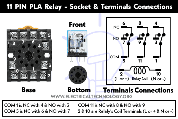
Connections of 11-Pin Relay Terminals:
As shown in fig, the 11-pin relay terminals are interconnected with the following pin configuration:
- Pins 2, 10: Relay’s Coil Connections ( L or + and N or – = energizing the coil)
- Pin Common (COM) 1 is normally closed (NC) with 4 and Normally Open (NO) with 3.
- Pin Common (COM) 5 is normally closed (NC) with 6 and Normally Open (NO) with 7.
- Pin Common (COM) 11 is normally closed (NC) with 8 and Normally Open (NO) with 9.
Latching or Holding Circuit Using 11-PIN PLA Relay
Below is the step-by-step guide to wire a holding or latching circuit using 11-pin relay.
- Connect the phase wire from the two-poles MCB (100-230V AC breaker) to the 2 & 7 terminals of the relay.
- Similarly, wire the neutral wire from the MCB to the 10 terminal of the relay.
- Connect two pushbuttons (NC and NO) in series with the phase wire from the CB to the relay’s terminals 2 & 7.
- Connect a direct wire from the phase (from MCB and right before the Stop push button) to the 11 and 6 terminals of the relay.
- Connect a holding wire from the 2nd terminal of NC (or starting terminal of NO pushbutton) to the 3 terminal of the relay.
- Finally, connect the output wires from terminals 8 and 6 of the relays to two light bulbs.
- Lastly, connect the neutral and ground/earth wire to both light bulb holders. The circuit is complete.

Without interlocking or holding circuit, pressing the red NC button will only complete the circuit while it is being held. When the button is released, the circuit will open, and the relay operation will be reversed.
However, when we apply the holding wire for interlocking, it will maintain the circuit, causing the light bulb to glow when we press the red pushbutton, and even when we release it. The same principle applies to the green pushbutton and its associated light bulb.
Purpose of Interlocking:
Interlocking is a critical safety feature in control systems that prevents certain combinations of operations or conditions that may lead to hazardous situations. By using interlocking circuits, we can establish a logical connection between different devices, making sure they operate in a predefined sequence. This prevents unintended operations and safeguards the equipment, personnel, and the overall system.
The primary purpose of the relay holding circuit (also known as interlocking circuit) is to maintain a particular state of the relay contacts after the coil is de-energized. It ensures that the relay remains latched in its last position until a specific action is taken to release it. This feature is particularly useful in applications where a momentary loss of power should not affect the continuity of the controlled circuit.
The interlocking wiring connection involves connecting the NO and NC contacts of different relays together. When the coils of these relays are energized, the corresponding NO contacts will close. Conversely, when the coils are de-energized, the NC contacts will open. This arrangement creates a logical interlock, allowing us to control devices or processes that require sequential operation.
How to Interlock two 11-Pins Relay?
Step 1: Identify the Relays
Identify the relays that need to be interlocked. For demonstration purposes, we’ll consider two relays: Relay A and Relay B.
Step 2: Wiring the Coil Circuit
Connect the coils of Relay A and Relay B to their respective control signals. Depending on the application, this could be a push-button, a PLC (Programmable Logic Controller), or any other suitable control device.
As shown in the diagram, connect the neutral wire from 230V MCB to the terminal # of 10 of both Relays. Now, Connect the phase wire from the MCB to the common terminal of 11 (relay A).
Step 3: Wiring the NO Interlocking Contacts
Connect the contact # 11 and 3 of Relay B to the terminal # 3 of Relay A. This means that when Relay A is energized, its NO contact will close, energizing the coil of Relay B.
Step 4: Wiring the NC Interlocking Contacts
Connect the NC (Normally Closed) contact # 8 of Relay B to the coil circuit of Relay A terminal #2 and common terminal 1. This ensures that when Relay B is energized, its NC contact will open, preventing Relay A from being energized simultaneously.
Step 5: Complete the Loop
To establish a complete interlocking circuit, you need to connect the common terminals of the NO and NC contacts to the control voltage source (e.g. 230V AC, or in case of DC, the positive side of the power supply). Additionally, connect the normally open terminals of both relays to the negative side of the power supply.
Relay Holding Circuit Diagram:
To visualize the interlocking wiring connection and the relay holding circuit diagram, consider the following schematic:
Diagram
In this diagram, the coil circuits of Relay A and Relay B are connected as per diagram. The interlocking connection ensures that Relay A and Relay B cannot be simultaneously energized, thereby preventing any conflicting operations.
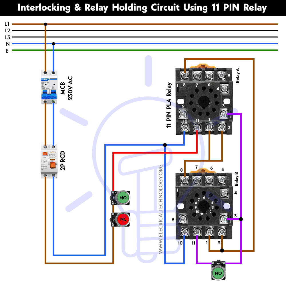
Furthermore, you may connect the load to either the NC or NO terminals of both relays, depending on the circuit requirements, design, and applications.
Applications:
The 11-pin relay interlocking wiring connection finds applications in various industries and control systems, including:
- Motor Control: Preventing simultaneous start/stop commands to avoid damage to machinery.
- Conveyor Systems: Ensuring sequential operation to prevent collisions or jams.
- Process Control: Maintaining safe and efficient process sequences in manufacturing plants.
- Safety Systems: Implementing emergency stop interlocks to protect personnel and equipment.
Related Posts:
- How to Wire 8-PIN Relay for Holding or Latching Circuit?
- ON / OFF 3- Phase Motor Using 8-PIN Relay and DOL Starter
- Automatic ON/OFF Circuit Using Two 8-PIN Timers for 1 & 3-Φ Load
- How to Wire 14-PIN Relay for Holding or Latching Circuit?
- ON / OFF 3- Phase Motor Using 14-PIN Relay and DOL Starter
- How to Control a Three-Phase Motor Using Solid-State Relay?
- Sequential Motor Control Circuit Using ZEN Programable Relay


