Wiring a 12kW Level 2 ChargePoint Home Flex Charger using Hardwired and Plug-in Connections for Every EV Charging
ChargePoint Home Flex EV Charger
The ChargePoint® Home Flex is a versatile Level 2 home EV charger developed by Eaton and ChargePoint. It can be configured from 16A to 50A charging with 20A to 80A breaker rating at 240V in hardwiring, while it can be used for 40A charging in plug-in installations. The CPH50 charger is designed to charge virtually any electric vehicle, including Tesla models, through either the J1772 (universal) connector or the NACS (Tesla) connector variants.
The charger can be configured for different charging current levels to match the available circuit capacity. Its high-speed Level 2 AC charging capability can provide up to 37 miles of driving range per hour of charging when configured for 50A operation.
The unit can be installed as a permanent hardwired connection or as a plug-in charger using either a NEMA 6-50 or NEMA 14-50 receptacle. In addition, the charger supports smart features and can be monitored and controlled remotely through the ChargePoint smartphone app.
Click image or open in a new tab to enlarge
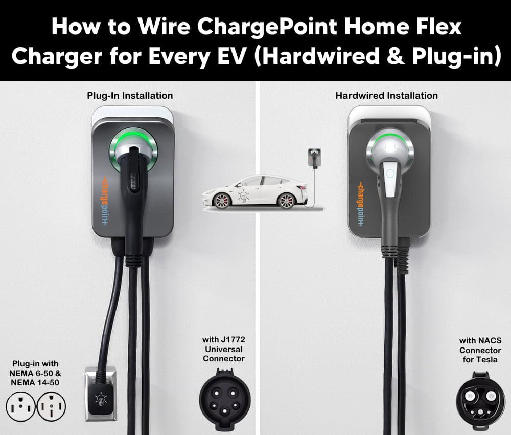
The available models, connector types, and wiring configurations are as follows:
- E99-003909: Hardwired installation with J1772 connector
- E99-003920: Hardwired installation with NACS connector
- E99-003812: NEMA 14-50 plug-in installation with J1772 connector
- E99-003813: NEMA 6-50 plug-in installation with J1772 connector
- E99-003918: NEMA 6-50 plug-in installation with NACS connector
- E99-003919: NEMA 14-50 plug-in installation with NACS connector
Electrical Ratings & Specifications
- Name: ChargePoint® Home Flex Charger – CPH50
- Voltage: 208-240V AC – 60 Hz – Single-Phase
- Breaker Rating: 20A to 80A – Setting depends on the charging current
- Charging Current: 16A, 24A, 32A, 40A, 48A, 50A – Adjustable
- Output Power: Up to 12 kW at 50A, 240V
- Charging Speed (est.): Up to ~37 miles of range per hour at 50A
- GFCI: 20 mA CCID with Auto Retry
- Wire Size: (Hardwire) = 6 AWG copper
- Connector Type: SAE J1772 (Universal) or SAE J3400 – NACS (Tesla-style) with 23ft (7 m) Cable
- Connectivity: 2.4 GHz Wi-Fi (802.11 b/g/n) Wi-Fi – Managed via the MyLeviton App
- Listed: UL 2594, UL2231-1, UL2231-2. NEC article 625 compliant and cUL listed.
- Wiring Method: Hardwired, or Plug-in via NEMA 14-50 or NEMA 6-50 Plugs & Receptacles
- Enclosure: NEMA / UL Type 3R rated for Indoor / Outdoor Mounting as per UL 50E.
Circuit Rating, Max Load & Charging Range
The breaker/circuit rating determines the maximum amperage the charger can be set to. Per NEC continuous-load rules (NEC -210.19(A)(1), the Home Flex must be set so its load never exceeds 80% of the circuit breaker’s rating. In other words, the breaker must be rated at no less than 125% of the charger’s continuous load).
The following table shows the breaker size, charging current, output power and estimated charging range per hour at 240V AC supply.
| Breaker Size | Charging Current | Output Power | Est. Range/Hour |
| 70A | 50A | 12 kW | 37 mi / 60 km |
| 60A | 48A | 11.5 kW | 36 mi / 58 km |
| 50A | 40A | 9.6 kW | 30 mi / 48 km |
| 40A | 32A | 7.68 kW | 25 mi / 40 km |
| 30A | 24A | 5.7 6kW | 18 mi / 29 km |
| 20A | 16A | 3.84 kW | 12 mi / 19 km |
Good to Know: Plug-in installation with a NEMA 14-50 or 6-50 receptacle is only permitted on a 40A or 50A breaker (32A or 40A charging, respectively). Every other amperage setting (e.g. 16A, 24A, 48A, and 50A charging) requires a hardwired installation. In Canada, plug-in installation is permitted only on a 50A circuit.
The ChargePoint Home Flex (CPH50) can be installed in either indoor or outdoor locations using one of the following three wiring methods:
- Hardwired Installation (Direct Connection)
- Plug-in Installation using a NEMA 6-50 Receptacle
- Plug-in Installation using a NEMA 14-50 Receptacle
Method 1: Hardwired Installation
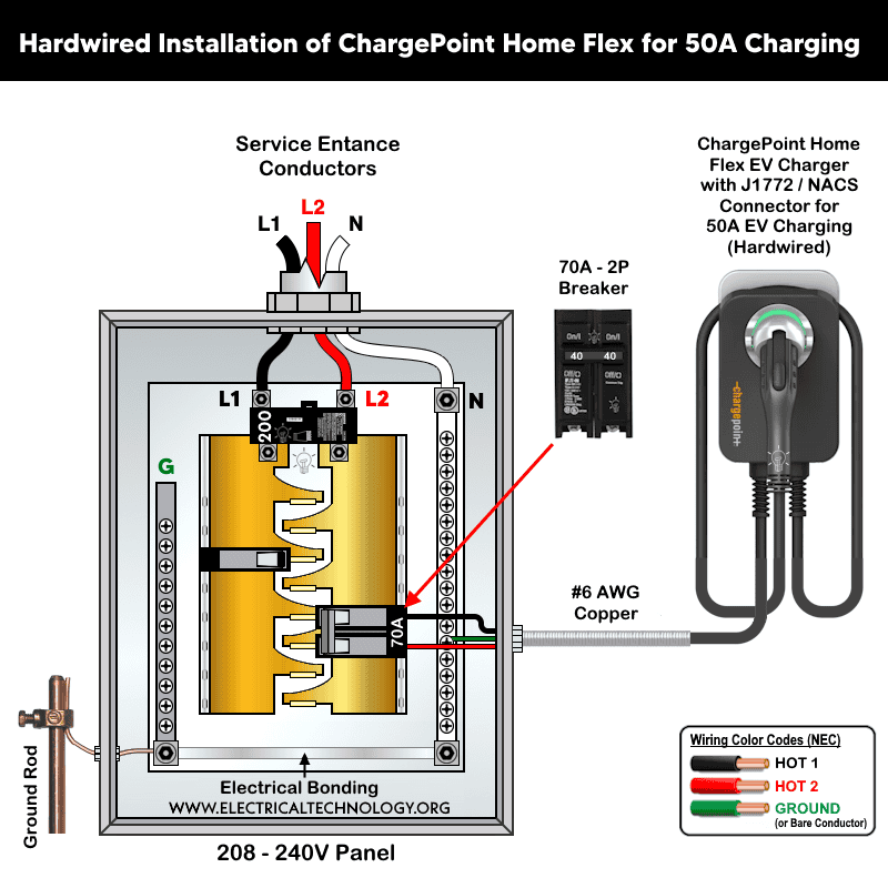
ChargePoint and Eaton recommend hardwiring whenever possible because it supports the full 20A-80A breaker range for 16A and maximum 50A charging. The direct connection method works with any outdoor installation, and avoids the GFCI nuisance-tripping issues sometimes seen with plug-in installs.
For hardwired (direct connect) installation, follow the following steps:
- De-energize the circuit: Switch off the breaker for the 240V circuit at the panel. Do not restore power until installation is fully complete.
- Remove the faceplate and pre-installed power cord if present. If your unit shipped with a pre-installed NEMA power cord, remove the plug assembly by lifting the three white levers (cable retainer clip) on the left side of the terminal block, then lift and pull out the cable clip. Needle-nose pliers make clip removal easier. Retain the cord in case you need it later.
- Mark the mounting centerline. Draw a vertical line centered on a stud (or other structurally suitable surface) at 1.0–1.1 m (39–43 in) above the floor.
- Dry-fit the station and drill the holes. Hold the station against the wall, centered on the mark (top of unit ≈1.3 m / 50 in above floor). Mark the two lower mounting and template’s top holes through the station’s holes, then set the station aside. For three mounting holes, use the included 4 mm (3/16 in) drill bit. Now, Drive a lag screw into the top-most hole, leaving a 3 mm (⅛ in) gap so the station can hang on it. Set the remaining two screws aside for later.
- Route the conductors before hanging (if entering from the rear). If bringing power through the rear knockout, remove the rear knockout plug and route conductors through before hanging the station. On exterior walls, apply sealant around the rear knockout to prevent water ingress.
- Mount the charger. Hang the station on the top screw using the rear notch, then drive the remaining two lag screws into the bottom mounting holes.
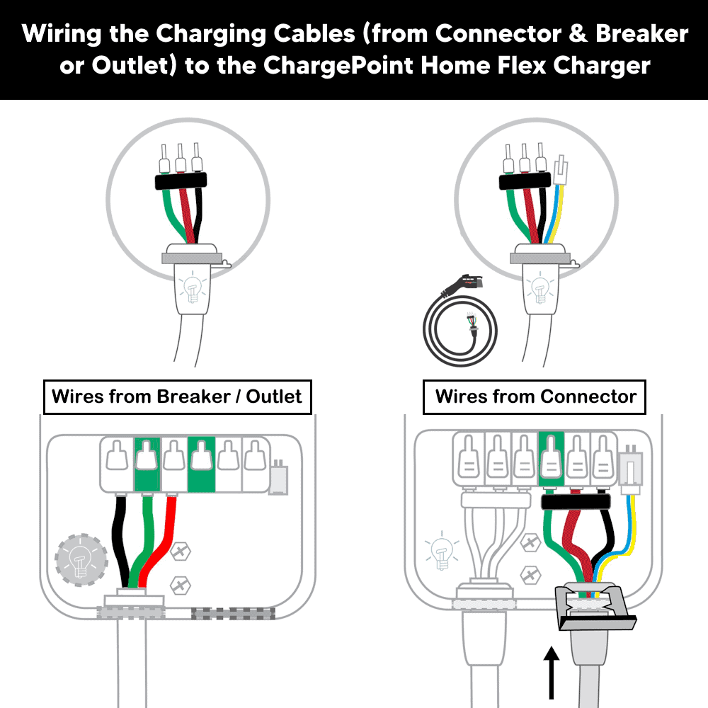
- Land the conductors in the terminal block. The conduit may enter the station through either the bottom or rear 19 mm (¾ in) knockout. Ensure the service wiring can comfortably reach the input terminal block, tighten the locknut on the conduit fitting, then strip each conductor 12 mm (½ in). Now, Lift the white levers to open the terminal block. Insert wires fully into the left-side connectors with the order, left-to-right: L1 (Line 1) → GND (Ground, center) → L2 (Line 2) (as shown in fig). Press each lever down firmly until it snaps shut to lock the conductor in place, then tug gently on each wire to confirm a secure connection.
Click image or open in a new tab to enlarge
Good to Know:
- The installation process is not completed yet. Once the input conductors are landed, proceed to Section 5 (Install the Charging Cable & Mount) to complete the charging-cable side of the wiring before powering up.
- The terminal-block levers snap shut with significant force. Keep fingers clear from underneath the levers while closing them.
- Seal any unused knockout with the plug provided in the box to maintain the enclosure’s NEMA 3R rating.
NEC Considerations for Hardwired Installs
- Article 625.54 (GFCI Protection for Personnel): a receptacle installed for EV charging must have GFCI protection; a direct (hardwired) connection is not required to add upstream GFCI protection unless the equipment manufacturer’s instructions call for it. In the current models of the ChargePoint Home Flex chargers, an internal CCID (Charge Circuit Interrupting Device) is provided to offer personnel protection on hardwired circuits.
- Article 625.42 (continuous load): size the branch circuit conductors and overcurrent device for 125% of the charger’s maximum configured output, consistent with general continuous-load sizing rules in Article 210.19/210.20.
- Article 625.43 (disconnecting means): a readily accessible disconnect – typically the branch breaker itself, if visible from the charger – must be available; equipment rated above 60A or 150V to ground needs a lockable disconnect.
- Article 210.8 (GFCI by location): independent of 625.54, a receptacle located in a garage, outdoors, or another listed location may separately trigger GFCI requirements; evaluate both 625 and 210.8 since either can apply.
- Article 625.56 (wet locations): any receptacle used in a wet location needs a weatherproof, in-use-rated enclosure.
Note: Always confirm current local-jurisdiction amendments – NEC adoption and AHJ interpretation vary by state and municipality.
Method 2.1: Plug-In Wiring with a NEMA 6-50 Receptacle
The NEMA 6-50 is a 2-pole, 3-wire, 250V, 50A receptacle commonly used for welders. Because the Home Flex doesn’t require a neutral, NEMA 6-50R (without neutral) is recommended for ChargePoint which can slightly reduced the cost of the new plug-in circuit run compared to NEMA 14-50R, since one fewer conductor is needed.
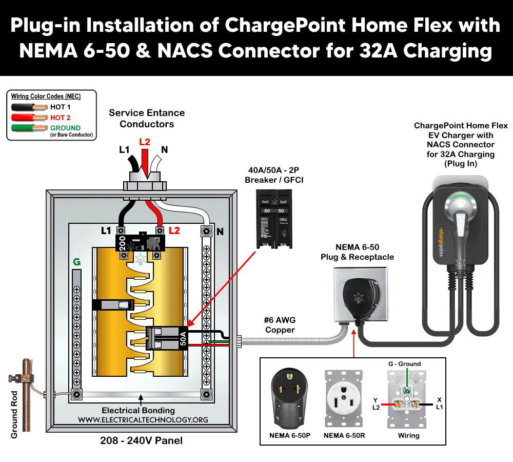
To wire the NEMA 6-50 receptacle, connect the THHN/THWN-2, #6 AWG three conductors (2 hots (L1, L2) + Ground) from a 2-pole, 50A standard breaker for 40A charging as follow:
- X (Brass screw) to L1 i.e. Hot 1 (Black wire)
- Y (Brass screw) to L2 i.e. Hot 2 (Red wire)
- G (Green screw) to Ground (Green/Bare wire)
To do so,
- Run a dedicated 3-conductor circuit (2 hots, ground – no neutral needed) sized to a 50A two-pole breaker from the panel to the receptacle location.
- Install the NEMA 6-50 receptacle with branch circuit conductors, landing L1 and L2 on the two hot terminals and the ground conductor on the green ground terminal. Tighten all terminal screws to specified torque.
- Install a dedicated, non-GFCI, two-pole 50A breaker in the panel, and apply the matching amperage label.
- Mount the charger per the instructions given below the method 2.1 (for both receptacles), then plug the charger’s input cable into the 6-50 receptacle once wiring is complete and the station is fully mounted.
- Set the charging amperage to 40A using the ChargePoint Installer app (Section 6) before commissioning.
Click image or open in a new tab to enlarge
Recommendation: For new installations, use hardwired installation whenever possible. If a plug-in installation is desired, choose NEMA 6-50 over NEMA 14-50 unless a NEMA 14-50 outlet already exists.
2.2 Plug-In Wiring with a NEMA 14-50 Receptacle
The NEMA 14-50 is a 3-pole, 4-wire, 125/250V, 50A receptacle widely used for electric ranges, RV pedestals and EV charging. The industrial grade (EV rated) 14-50 outlet can be used for 50A, 40A and 32A charging. For instance, if the outlet is protected by a 40A breaker (due to panel capacity), the charger can be used for continuous charging of 32A current.
Although a NEMA 14-50 receptacle supplies four conductors (L1, L2, neutral, and equipment ground), the ChargePoint Home Flex EV charger does not need the neutral conductor. The charger has no internal loads or circuitry that require a line-to-neutral voltage and operates exclusively from the 240V line-to-line supply.
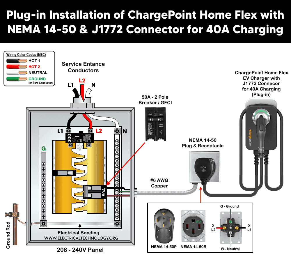
To wire an industrial-grade NEMA 14-50 receptacle, connect the THHN/THWN-2, #6 AWG copper, four conductors (2 hots (L1, L2) + Neutral + Ground) from a 2-pole, 50A standard/GFCI breaker for 40/50A charging as follow:
- X (Brass screw) to L1 i.e. Hot 1 (Black wire)
- Y (Brass screw) to L2 i.e. Hot 2 (Red wire)
- W (Silver screw to Neutral (White wire)
- G (Green screw) to Ground (Green/Bare wire)
For the rest of hardwired installation, follow the following steps:
- Run a dedicated 4-conductor circuit (2 hots, neutral, ground) sized to a 50A two-pole breaker from the panel to the receptacle location.
- Install the NEMA 14-50 receptacle with L1 and L2 on the two hot terminals, the neutral on the silver/white terminal, and the ground conductor on the green ground terminal. Torque all terminal screws to the receptacle manufacturer’s specification
- Install a dedicated, standard (or GFCI if needed by code), two-pole 50A breaker in the panel, and apply the matching amperage label.
- Mount the charger per the instruction (given in below section), then plug the charger’s input cable into the 14-50 receptacle once wiring is complete and the station is fully mounted.
- Set the charging amperage to 40A using the ChargePoint Installer app (Section 6) before commissioning.
Click image or open in a new tab to enlarge
Instructions and Code Requirements (For both Receptacles)
Reusing and Existing Outlet
Many existing garage 240V outlets (e.g., dryer circuits) use receptacle types that do not match either 14-50 or 6-50. If it doesn’t match (residential grade instead of industrial or EV rated), plan to either install a new dedicated 14-50/6-50 circuit or switch to a hardwired installation instead.
Notes:
Some Home Flex configurations include a factory-attached NEMA 14-50 plug rather than bare leads, in that case you only need to wire and mount the matching receptacle, the charger’s own cord simply plugs in.
Mount the your chosen 14-50 or 6-50 receptacle 500–600 mm (20–26 in) above the floor, adjacent to the stud where the charging station will hang i.e. close enough that the charger’s 0.3 m (12 in) input power cable can reach it without strain. After that, continue to section 5 (install the Charging Cable & Mount).
Whichever receptacle type you choose, the Home Flex must have its own dedicated circuit – never share a circuit between two charging stations, or between a charger and another appliance such as a dryer.
Outdoor installation requires either a hardwired connection or an outdoor-rated, weather-resistant electrical outlet. The Home Flex enclosure itself is NEMA 3R-rated for outdoor exposure, but the receptacle (if plug-in) must independently carry a weatherproof rating.
If your local jurisdiction requires a GFCI breaker for a plug-in install, ChargePoint recommends switching to a hardwired installation instead. The Home Flex already includes integrated charging-circuit-interrupting-device (CCID) personnel protection, and stacking a panel-level GFCI breaker on top of it is a common cause of nuisance tripping that interrupts charging. This reflects the same tension found in NEC 625.54, which requires GFCI protection for personnel at cord-and-plug-connected EVSE receptacles, while direct (hardwired) connections are not required to add it unless the manufacturer’s instructions call for it.
Install the Charging Cable & Mount
This step is identical for both hardwire and plug-in installs, and connects the vehicle-side charging cable (J1772 or NACS) to the charger’s output terminal block.
1. Prep the Charging Cable.
Verify the breaker is off and the circuit is still de-energized before opening the output terminal block. Remove the cable clip from the wire end of the cable (retain it – you’ll reuse it) and lift the white levers to open the output terminal block.
2. Connect Branch Circuit Conductors.
Feed the charging-cable wires through the bottom hole of the station. Match the green (ground) wire to the ground terminal on the left side of the output block, then insert each wire into its corresponding terminal i.e. L1 (Hot1), Green in the middle (Ground) and L2 (Hot 2) as shown in fig.
3. Lock the conductors.
Press all three levers down until they snap into place. Keep fingers clear from underneath – they close with significant force.
4. Connect the cable’s data/communication connector.
Insert the white signal plug into the connector toward the right side of the terminal block.
5. Secure the strain relief and wire cover.
Push up on the charge-cable strain relief and slide the cable clip back into its slot to lock the cable mechanically in place. Use a coin to turn and lock the wire cover into place over the terminal compartment.
6. Re-apply the rating label.
Confirm the amperage rating label on the bottom of the station matches the configured circuit. i.e. apply the appropriate rating label (printed sheet given in the package) on both the charger and the branch circuit breaker such as 32A, 40A, 48A, 50A.
7. Dress the cable and dock the connector and restore power
Reinstall the faceplate over the connector opening. Drape the charging cable over the top of the station and dock the connector in its holster. Now, restore breaker power and verify LED transitions i.e. Yellow and Flashing white. The next step is to configure the setting in the ChargePoint Installer App.
Click image or open in a new tab to enlarge
Caution: As with the input terminal block, the output block’s levers snap shut forcefully. Keep fingers clear of the area beneath them while closing.
Power-Up, Commissioning & the Installer App
- After restoring the power at the panel, confirm the front status light glows yellow, then begins blinking white. This indicates the charger is in boot/setup mode (see Section 7 for the full status LED light reference).
- Download the ChargePoint Installer mobile App (iOS & Android).
- In the app, select Get Started, choose the installation type performed (hardwire, 14-50, or 6-50), and set the breaker/amperage rating to match the circuit you wired.
- On the main menu, click “Home Charger.” Select “Set Up Home Charger” from the Home Charger screen.
- Select “Activate” and follow the instructions in the app.
- Send the homeowner a setup notification through the app (via mobile or email).
Good to Know:
The licensed electrician sets the maximum current using the ChargePoint Installer app, but the homeowner must separately activate the station and complete setup using the consumer-facing ChargePoint app (distinct from the Installer app) – accessible via Home Charger → Set Up. If the breaker rating can’t be set in the Installer app, it can instead be set through the homeowner’s ChargePoint account in the consumer app.
If NO WI-FI AVAILABLE
ChargePoint strongly recommends connecting to Wi-Fi for full smart-charging functionality, but if Wi-Fi isn’t available at commissioning time, a licensed electrician can still set the amperage from the 16A default via Bluetooth.
Charging Station Status LED Lights
| LED Status | Indication |
| Solid Yellow | Updating software or booting up |
| Pulsing Yellow | Charger needs to be set up in the app |
| Solid Green | Ready to charge |
| Pulsing Green | On a schedule – plug in twice to charge immediately |
| Solid Blue | Plugged in |
| Pulsing Blue | Currently charging |
| Ring outline only (dim) | Not connected to Wi-Fi – check Wi-Fi in the app |
| Solid Red | Fault Detected – see Section 8 and the troubleshooting table |
Secondary Wi-Fi / Fault Indicators (on some units)
- Green indicator on = connected to Wi-Fi; green off = not connected.
- Red indicator on = fault detected; red off = no fault detected.
Fault Codes & Troubleshooting
If the station displays solid red, solid blue, or a fault transitions from blue to red, use the table below to identify the likely cause and first response. “Solid Blue → Solid Red after 1 min” entries only notify/escalate after that one-minute delay.
| Fault | LED Behavior | First Response |
| Immediate Ground Fault (IGF) | Solid Red | Remove and reseat the charging connector; if it recurs, the connector or cable may need replacement. |
| Soft Ground Fault (GF) | Solid Blue → stays blue past 15 min | Remove and reseat the charging connector; if it recurs, the connector or cable may need replacement. |
| Ground Monitor Fault (GMF / Earth Fault) | Solid Blue → Solid Red after 1 min | Restart by unplugging the charging cable or cycling the circuit breaker. |
| Relay Stuck Open (RSO) | Solid Blue → Solid Red after 1 min | Restart by unplugging the cable or cycling the breaker. |
| Over Current (OVRC) | Solid Blue | Vehicle is drawing more current than supported. Unplug the connector, wait ~15 sec, replug. If it recurs, contact the vehicle manufacturer. |
| Pilot Level Current Exceeded (PLCE) | Solid Blue | No specific consumer message – contact support if it persists. |
| Virtual Breaker – GFCI Coil (VBRGF) | Solid Red | Remove and reseat the charging connector. |
| Virtual Breaker – Current Coil (VRBI) | Solid Red | Remove and reseat the charging connector. |
| Pilot Voltage Error (PVERR) | Solid Blue → Solid Red after 1 min | Restart by unplugging the cable or cycling the breaker. |
| Self-Test Time Out (STTO) | Solid Blue → Solid Red after 1 min | Restart by unplugging the cable or cycling the breaker. |
| Frequency Error (FREQ) | Solid Blue → Solid Red after 1 min | Restart by unplugging the cable or cycling the breaker. |
| Ground Monitor Self-Test Error (GMERR) | Solid Blue → Solid Red after 1 min | Restart by unplugging the cable or cycling the breaker. |
| CPU Register Test Error (CERR) | Solid Blue → Solid Red after 1 min | Restart by unplugging the cable or cycling the breaker. |
| Program Counter Test Error (PERR) | Solid Blue → Solid Red after 1 min | Restart by unplugging the cable or cycling the breaker. |
| RAM Test Error (RERR) | Solid Blue → Solid Red after 1 min | Restart by unplugging the cable or cycling the breaker. |
| Flash Memory CRC Error (FERR) | Solid Blue → Solid Red after 1 min | Restart by unplugging the cable or cycling the breaker. |
FAQ:
What Amperage Should I install At?
32A and 40A are the most popular settings and suit most drivers. 48A and 50A charge fastest but may require a panel upgrade due to space limits and main breaker rating. If panel capacity is limited, a licensed electrician should select the highest amperage the panel can support.
Can I Increase the Amperage after Installation?
Only if your electrician upgrades the circuit (wire and breaker) to support the higher setting, and then reconfigures the charger via the Installer app. The homeowner can also use the ChargePoint app to manually throttle charging down to as low as 80% of the breaker’s rating without an electrician visit.
Can I Install Outdoors?
Yes – the enclosure is NEMA 3R-rated for outdoor use. Outdoor installs require either hardwiring or a weatherproof, in-use-rated receptacle.
Can I Reuse My Dryer Outlet?
Usually not directly – most dryer outlets use a NEMA configuration (e.g., 14-30) that doesn’t match the Home Flex’s 14-50/6-50 plug. An electrician may be able to repurpose the circuit at a lower hardwired amperage setting instead.
Do I Need a GFCI Breaker for Charge Point Home?
The Home Flex includes internal CCID personnel protection. ChargePoint does not recommend adding a panel GFCI breaker, as the combination tends to cause nuisance tripping. If your local code mandates a GFCI breaker for a plug-in install, switch to hardwiring instead. For outdoor plug-in installation, It is required by code to install upstream GFCI breaker.
Can Two Charging Stations Share One Circuit?
No. Each Home Flex requires its own dedicated branch circuit – never shared with another charger or another appliance.
Who Activates the Charger – The Electrician or the Homeowner?
The electrician sets the maximum current and commissions the hardware using the ChargePoint Installer app. The homeowner then activates the station and finishes setup in the separate, consumer-facing ChargePoint app.
Instruction and Precautions
- Disconnect the power supply to de-energize the circuit before installation.
- Make sure the installation complies NEC Article 625 for EV charging, plus applicable Articles i.e. 110, 210, 220, 240, and 310. In addition, follow your local Authority Having Jurisdiction (AHJ) if applicable.
- Per NEC Article 625, the EV connector holster must be mounted between 18 in. (450 mm) and 4 ft (1.2 m) above floor level indoors, and at least 24 in. (600 mm) above grade outdoors.
- In regions with frequent thunderstorms, add surge protective devices (SPD) at the service panel.
- Install in accordance with the National Electrical Code (NEC), the Canadian Electrical Code (CEC), and all applicable local amendments. Check with your local electrical inspector before starting.
- This equipment must be installed, adjusted, and serviced only by qualified and licensed electrician who is familiar with this type of equipment and its hazards.
- Failure to follow these instructions could result in death, personal injury, or property damage.
Disclaimer:
The author will not be liable for any losses, injuries, or damages from the display or use of this information or if you try any circuit in wrong format. So please! Be careful because it’s all about electricity and electricity is too dangerous. If you are unsure, contact a licensed electrician to do it according to the local area codes.
Resources:
EV Charger Wiring Series
- How to Wire AC Level 2 EV Smart Breaker Charger – 40A/32A
- How to Wire an EV Wall Charger – Hardwired and Plug-in
- How to Wire Smart Electric Vehicle Charging Station – 32A/80A
- How to Wire 48A Level 2 Dual Port EV Charging Station
- How to Wire and Use Tesla Gen 3 Mobile Connector Charger
- How to Wire a Tesla Wall Connector & Universal EV Charger
Smart Devices Wiring Series
- How to Wire a Smart Switch in a 120/240V Load Center
- How to Wire 120/240V Smart Load Center with Smart Breakers
- How to Wire a Smart Breaker in a Smart 120/240V Panel
- How to Wire a Smart GFCI Breaker in a 120/240V Smart Panel
- How to Wire Smart AFCI/GFCI Breaker in a Smart Load Center
- How to Wire a 15A Wi-Fi Smart Outlet in a Smart Panel
- How to Wire 15A and 20A Wi-Fi Smart GFCI Outlets
- How to Wire Z-Wave Smart Switch, Dimmer & Fan Speed Controller
- How to Wire a Digital and Wi-Fi Smart LED Dimmer Switch
- How to Wire a Smart Switch Companion with a Smart Switch
- Wiring a Smart Dimmer Switch Companion with a Digital Dimmer
- How to Install a Wire-Free Smart Dimmer Anywhere Companion
- How to Wire Smart Scene Controller Switch
- How to Install a Wireless Smart Scene Switch
- How to Install a Wake and Sleep Wireless Smart Switch
- How to Wire a Smart Motion Sensing Dimmer Switch
- How to Wire a Combo Humidity Sensor & Fan Control with Light Switch
- How to Wire Humidity Sensor and Fan Control Switch
- How to Wire a Countdown Timer Switch – 15 Mins to 12Hrs
Wiring Standard GFCI & Breakers
- How to Wire a 1-Pole Breaker
- How to Wire a 2-Pole Breaker
- How to Wire a 3-Pole Breaker
- How to Wire a 1-Pole GFCI
- How to Wire a 2-Pole GFCI
- How to Wire a 3-Phase, 3-Pole GFCI
- How to Wire a Tandem Breaker
- How to Wire GFCI Circuit Breakers
- How to Wire an AFCI Breaker
Main Panels Wiring Tutorials
- How to Wire 120V/240V Main Panel? Breaker Box Installation
- How to Wire 120/240V Smart Load Center with Smart Breakers
- How to Wire 208V/120V, 1-Phase & 3-Phase Main Panel?
- How to Wire 240V, 208V & 120V, 1 & 3-Phase, High Leg Delta Main Panel?
- How to Wire 277V/480V, 1-Phase & 3-Phase Main Service Panel?
- How to Wire a Subpanel? Main Lug Installation for 120V/240V
- Single Phase Electrical Wiring Installation in Home according to NEC & IEC
- Three Phase Electrical Wiring Installation in Home – NEC & IEC
- How To Wire a Single Phase kWh Meter – 120V/240V
- How to Wire a Three-Phase Meter? 120/208/240/277/347/480/600V
- How to Wire Spa Panel for Hot Tub using 2-P GFCI & Breaker
Wiring General Outlets & GFCI/AFCI Receptacles
- How to Wire an Outlet Receptacle? Socket Outlet Wiring Diagrams
- How to wire a GFCI Outlet?
- How to Wire an AFCI Outlet?
- How to a Wire 3-Way Combination Switch and Grounded Outlet?
- How to Wire a 15A – 125V Outlet – NEMA 5-15 Receptacle
- How to Wire a 20A – 125V Outlet – NEMA 5-20 Receptacle
- How to Wire a 15A – 250V Outlet – NEMA 6-15 Receptacle
- How to Wire a 20A – 250V Outlet – NEMA 6-20 Receptacle
- How to Wire a 30A – 250V, NEMA 6-30 Receptacle
- How to Wire a 50A – 125/250V Outlet – NEMA 14-50 Receptacle for EVs
Sizing Breakers, Wires & Panels
- How to Size a Load Center, Panelboards and Distribution Board?
- How to Determine the Right Size Capacity of a Subpanel?
- How to Find the Right Wire Size for 100A Service 120V/240V Panel?
- How to Size a Circuit Breaker?
- How to Find the Proper Size of Wire & Cable In Metric & Imperial Systems
- How to Size a Breaker and Wires in AWG with EGC for Load?
- How to Size Service-Entrance Conductors and Feeder Cables?
- How to Size Feeder Conductors with Overcurrent Protection
- How to Size a Branch Circuit Conductors with Protection?
- How to Size Equipment Grounding Conductor (EGC)?
- How to Size Grounding Electrode Conductor (GEC)?
- How to Size Main Bonding Jumper (MBJ)?
- How to Size Motors FLC, HP, Voltage, Breaker Size and Wire Size
- What is the Correct Wire Size for 100A Breaker and Load?
- What is the Right Wire Size for 15A Breaker and Outlet?
- What is the Suitable Wire Size for 20A Breaker and Outlet?
-
 BYD Orders 10 More Ships to Carry 130,000+ EVs Worldwide
-
 BYD Launches Electric Truck to Rival Tesla Semi in Europe
-
 BYD’s New Electric Truck for EU Beats Tesla Semi in Almost Every Metric
-
 Windrose Electric Trucks Enter Australia’s Long-Haul Freight
-
 Germany’s Electric Drone Hits 699 km/h, Eyes World Record
-
 How to Wire and Use Tesla Gen 3 Mobile Connector Charger