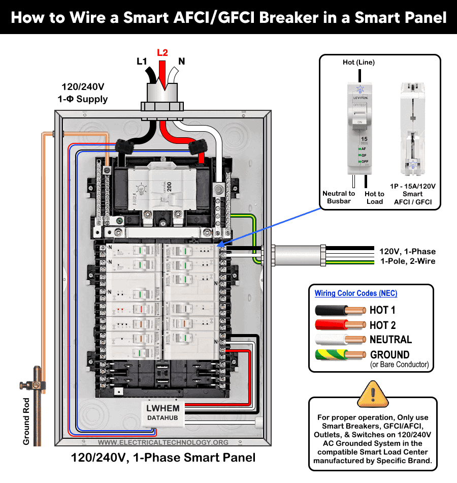
How to Wire Smart AFCI/GFCI Breaker in a Smart Load Center
How to Wire Combination of Smart AFCI/GFCI Breakers in a 120/240V Smart Electric Panel
What is a Dual-Function AFCI/GFCI Breaker?
A dual-function AFCI/GFCI breaker is a circuit breaker that combines both Arc-Fault Circuit-Interrupter (AFCI) protection and Ground-Fault Circuit-Interrupter (GFCI) protection in a single device. It is installed in the service panel and protects the entire branch circuit from the breaker to the last outlet. This type of breaker is commonly used to meet safety requirements in the National Electrical Code where both forms of protection are mandated.
The AFCI portion of the breaker is designed to detect dangerous arcing conditions in wiring, such as those caused by loose connections, damaged conductors, or deteriorated insulation. Arc faults can generate high temperatures capable of igniting surrounding materials, creating a fire hazard. When abnormal arcing signatures are detected, the breaker trips to interrupt the circuit and reduce fire risk.
The GFCI portion monitors the current flowing between the ungrounded (hot) and grounded (neutral) conductors. If it detects an imbalance (typically around 5 milliamps) indicating current leakage to ground, it trips almost instantly to protect people from electric shock. By combining both technologies into one device, a dual-function breaker provides comprehensive protection against both fire and shock hazards on the same circuit.
Code Requirements:
The NEC does not explicitly state, “use a dual-function breaker.” However, NEC 210.8 requires GFCI protection, while NEC 210.12 requires AFCI protection in areas such as bedrooms, kitchens, laundry rooms, and similar locations. When a branch circuit requires both types of protection, a dual-function breaker that provides both AFCI and GFCI protection is typically the most practical solution, rather than installing separate devices.
As the code requires both both arc-fault protection and ground-fault protection for 15A/20A – 120V branch circuits in such areas, a single dual-function breaker a compliant, efficient solution for the entire circuit.
In a dwelling unit, If the circuit is in a living area (AFCI zone) and it serves a location listed in 210.8 (GFCI zone), you need both protections.
All 120V, 15A & 20A receptacle circuits serving kitchen countertops require both AFCI and GFCI protection. In this case, electrician installs an AFCI breaker + GFCI receptacle or a dual-function breaker to comply with 210.8 for GFCI and 210.12 for AFCI protection.
Smart AFCI/GFCI Breakers
Similar to smart branch circuit breakers and smart GFCI breakers, dual-function smart AFCI/GFCI breakers are available from manufacturers such as Leviton. These plug-on, second-generation AFCI/GFCI branch circuit breakers with remote-control capability are available in 15A (LB115-DST) and 20A (LB120-DST) ratings for 120V circuits, with a short-circuit current rating (SCCR) of 10 kA.
They integrate with the My Leviton app, allowing remote ON/OFF control, scheduling of breaker operation, and monitoring of operational history to support home energy management and automation.
Wiring a Combo of Smart AFCI/GFCI Branch Circuit Breaker
Installing AFCI/GFCI Breaker
- Turn OFF the main breaker in the main panel or upstream disconnect. Confirm power is OFF using a contact-less tester.
- Remove the panel cover to access the breaker mounting area. 1-P breaker snap over a single slot (busbar) and occupies 1 space in the panel.
- Place breaker handle to OFF and snap it onto the panel bus.
- Terminate all connections about 25 in.-lbs or as per torque value given on the back side of the device.
Click image or open in a new tab to enlarge
Wiring Load Conductors
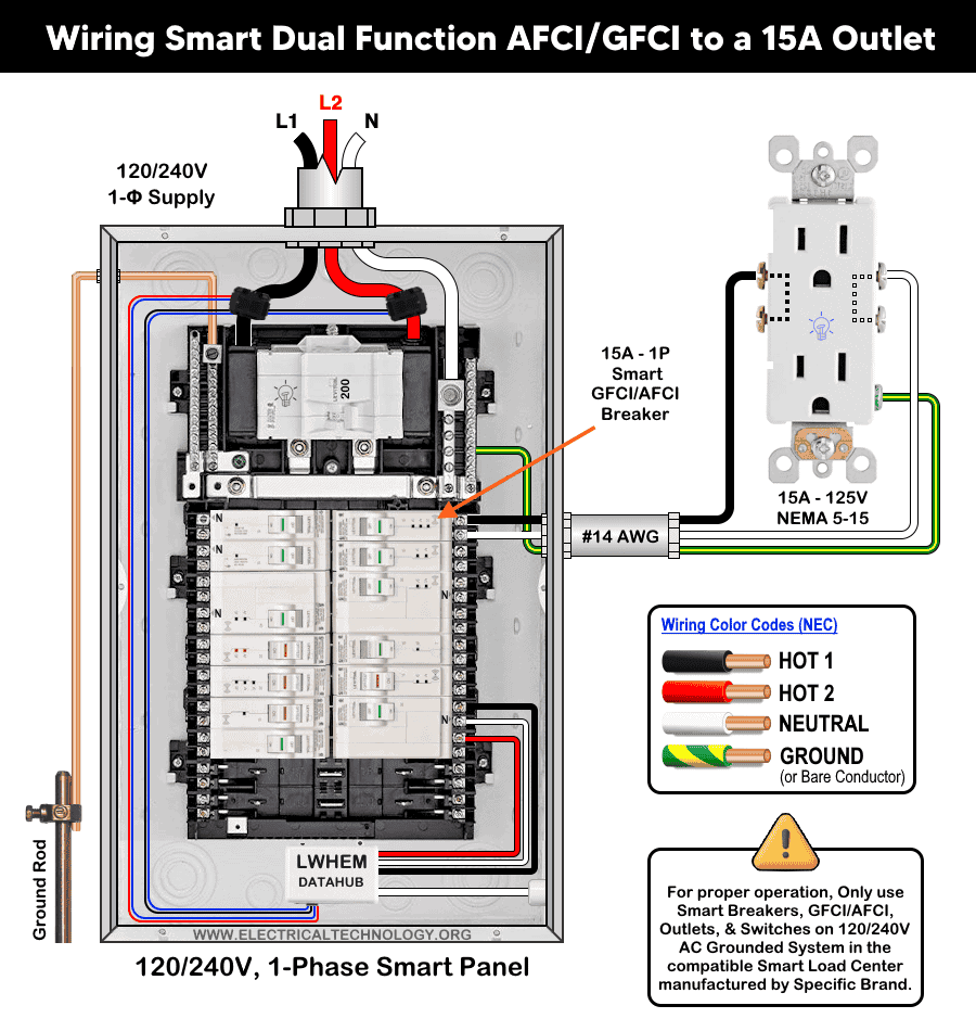
Since the 2nd generation smart combo of AFCI/GFCI breakers are available only as 1-Pole with current rating of 15A and 20A, hence, the wiring method is same i.e.
Strip 0.4 inch (≈10 mm) of insulation from the load conductor and connect as to the breaker as follow.
- Connect the Hot (black) conductor from the load to the brass screw of breaker
- Connect the Neutral (white) conductor from the load to the silver screw of the beaker.
- Connect the Ground (bare or green) from the load to the ground busbar in the main panel.
This configuration is shown in the following wiring diagram, where a 1-pole, 120V 2nd generation smart AFCI/GFCI breaker is wired with #14 AWG conductors to protect a 15A/120V (NEMA 5-15) standard outlet.
Click image or open in a new tab to enlarge
Replace panel covers to make sure labels/handles are visible. Restore power at the main breaker and turn the smart GFCI/AFCI breaker ON. If the breaker doesn’t stay ON or trips immediately, re-verify neutral and load wiring. For troubleshooting, refer to the LED status indicator section given below.
Testing
Turn main breaker or sub-panel feeder breaker ON to restore panel power. Move the AFCI/GFCI breaker handle from OFF to the the ON position.
- If the breaker stays ON and the handle window shows green, wiring is correct and the unit is operational.
- If it will not reset, recheck wiring, check the LED status indicator troubleshooting table or consult an electrician.
Diagnostic Table of LED Status Indictor
The following table shows the troubleshooting and diagnostic of smart AFCI/GFCI breakers using the LED status indicator on it.
| Smart AFCI/GFCI Breaker LED Status Indicator | ||||
| Breaker Handel | AF LED | GF LED | ON/OFF LED | Device Status |
| Green | OFF | OFF | OFF | ON |
| Green | OFF | OFF | ON – Solid | Remote OFF |
| Red | OFF | OFF | OFF | Short-circuit / Overload Trip |
| Red | ON Solid | OFF | OFF | Series Arc Fault Trip |
| Red | OFF | On – Solid | OFF | Ground Fault Trip |
| Red | ON – Blinking
OFF |
OFF
ON – Blinking |
OFF |
|
| Red | ON – Blinking | ON – Blinking | OFF | 0.1 Sec. Delay – Replace Breaker |
| White | OFF | OFF | OFF | Manual OFF |
Precaution:
- Always disconnect the power supply by switching OFF the main breaker before performing any electrical work.
- Never install AFCI, GFCI, AFCI/GFCI or GFPE breakers on circuits with shared neutrals, false or unwanted trips will occur.
- Do not use AFCI/GFCI branch circuit breakers for life-support equipment in hospitals and health services units because the nuisance tripping of the device will cut power to the equipment.
- GFCI/AFCI must be installed using copper / copper-clade conductors only.
- If you are unsure about any step, consult a licensed electrician to ensure the installation complies with applicable local electrical codes and regulations.
- Exercise extreme caution when working with electricity. Improper handling can result in serious injury, property damage, or death.
- If you are unsure about any step, consult a licensed electrician to ensure the installation complies with applicable local electrical codes and regulations.
- The author assumes no liability for any loss, injury, or damage resulting from the use or misinterpretation of this information, or from improper installation of any circuit.
Resources:
Smart Devices Wiring Series
- How to Wire 120/240V Smart Load Center with Smart Breakers
- How to Wire a Smart Breaker in a Smart 120/240V Panel
- How to Wire a Smart GFCI Breaker in a 120/240V Smart Panel
Main Panels Wiring Tutorials
- How to Wire 120/240V Main Panel – Breaker Box Installation
- How to Wire 120V/208V, 1-Phase & 3-Phase Main Panel?
- How to Wire 120/208/240V High Leg Delta 1-Phase & 3-Phase Main Panel?
- How to Wire 277/480V, 1-Phase & 3-Phase Main Service Panel?
- How to Wire 347/600V, 1 and 3-Phase Main Service Panel?
- How to Wire a Subpanel? Main Lug Installation for 120V/240V
- How to Wire a Spa Panel Box for a Hot Tub using 2P GFCI & Breaker
- Single Phase Electrical Wiring Installation in Home – NEC & IEC
- Three Phase Electrical Wiring Installation in Home – NEC & IEC
- How To Wire a Single Phase kWh Meter – 120V/240V
- How to Wire a Three-Phase Meter? 120/208/240/277/347/480/600V
Wiring Smart / Standard GFCI & Breakers
- How to Wire a 1-Pole Breaker
- How to Wire a 2-Pole Breaker
- How to Wire a 3-Pole Breaker
- How to Wire a 1-Pole GFCI
- How to Wire a 2-Pole GFCI
- How to Wire a 3-Phase, 3-Pole GFCI
- How to Wire a Tandem Breaker
- How to Wire GFCI Circuit Breakers
- How to Wire an AFCI Breaker
Wiring Smart / General Outlets & GFCI/AFCI Receptacles
- How to Wire an Outlet Receptacle? Socket Outlet Wiring Diagrams
- How to wire a GFCI Outlet?
- How to a Wire 3-Way Combination Switch and Grounded Outlet?
- How to Wire a 15A – 125V Outlet – NEMA 5-15 Receptacle
- How to Wire a 20A – 125V Outlet – NEMA 5-20 Receptacle
- How to Wire a 15A – 250V Outlet – NEMA 6-15 Receptacle
- How to Wire a 20A – 250V Outlet – NEMA 6-20 Receptacle
- How to Wire a 50A – 125/250V Outlet – NEMA 14-50 Receptacle
Switches Wiring
- How to Wire Single Pole, Single Throw (SPST) as 2-Way Switch?
- How to Wire Single Pole, Double Throw (SPDT) as 3-Way Switch?
- How to Wire Double Pole, Single Throw Switch? Wiring DPST
- How to Wire Double Pole, Double Throw Switch? Wiring DPDT
- How to Wire Double Switch? 2-Gang, 1-Way Switch – IEC & NEC
- How to Wire 4-Way Switch (NEC) or Intermediate Switch as 3-Way (IEC)?
- How to Wire Auto & Manual Changeover & Transfer Switch – (1 & 3 Phase)
Sizing Breakers, Wires, and Panels
- How to Size a Load Center, Panelboards and Distribution Board?
- How to Determine the Right Size Capacity of a Subpanel?
- How to Find the Right Wire Size for 100A Service 120V/240V Panel?
- How to Size a Circuit Breaker?
- How to Find the Proper Size of Wire & Cable In Metric & Imperial Systems
- How to Size a Breaker and Wires in AWG with EGC for Load?
- How to Size Service-Entrance Conductors and Feeder Cables?
- How to Size Feeder Conductors with Overcurrent Protection
- How to Size a Branch Circuit Conductors with Protection?
- How to Size Equipment Grounding Conductor (EGC)?
- How to Size Grounding Electrode Conductor (GEC)?
- How to Size Main Bonding Jumper (MBJ)?
- How to Size Motors FLC, HP, Voltage, Breaker Size and Wire Size
- What is the Correct Wire Size for 100A Breaker and Load?
- What is the Right Wire Size for 15A Breaker and Outlet?
- What is the Suitable Wire Size for 20A Breaker and Outlet?
Finding the Number of Breakers/Outlets in a Circuit
- How to Determine the Number of Circuit Breakers in a Panelboard?
- How to Find the Number of Outlets on a Single Circuit Breaker?
- How to Find Voltage & Ampere Rating of Switch, Plug, Outlet & Receptacle
- How to Calculate the Number of Fluorescent Lamps in a Final Sub Circuit?
- How to Calculate the Number of Incandescent Lamps in a Final Sub Circuit?
- How to Determine the Number of Lighting Branch Circuits?
- How to Determine the Number of Branch Circuits? – 3 Ways
- How to Find the Number of Lights on a Single Circuit Breaker?
General Wiring Installation Tutorials:
- How to Toggle Electric Water Heater Between 120V and 240V?
- How to Wire 120V Water Heater Thermostat – Non-Simultaneous?
- How to Wire 240V Water Heater Thermostat – Non-Continuous?
- How to Wire 3-Phase Simultaneous Water Heater Thermostat?
- How to Wire Twin Timer for 120V/240V Circuits – ON/OFF Delay
- How to Wire ST01 Timer with Relay & Contactor for 120V/240V Motors?
- How to Wire Multifunction ON/OFF Delay Timer for 120V/240V Motors?
- Even More Residential Wiring Installation Tutorials


