How to Wire a 15A – 250V Outlet – NEMA 6-15 Receptacle
How to Install a Standard 15A – 250V Receptacle (NEMA 6-15) with Breaker and GFCI Protection
A NEMA 6-15 receptacle is a 2-P, 3-W, 250V – 15A grounding outlet. This 15A – 240V outlet is used for small to medium-duty 240V appliances and equipment that do not require a neutral connection. In other words, It only requires two hot wires and a ground. These outlets are generally found in commercial and industrial buildings, workshops and laboratories and occasionally in residential garages or basements (for specific 240V tools).
Example loads are air conditioners (window or wall units), commercial lighting equipment, laboratory instruments, HVAC control units ,small machine tools, bench power supplies
The NEMA 6-15 Outlets and Receptacles
A NEMA 6-15 receptacle is a 15-amp, 250-volt, 3-wire grounded outlet used for low-power 240V appliances. It features two parallel horizontal slots for blades for the hot wires (Hot1 and Hot 2) and a round ground pin. It is used in settings like garages, workshops, and commercial spaces for appliances such as air conditioners, welders, and heat guns. It is a suitable option where a standard 120V outlet is insufficient to deliver the same 15A power at 240V supply.
The corresponding plug to use with NEMA 6-15R is a NEMA 6-15P. It means, it is only allowed for 250V equipment and not for 120V loads. In addition, it must be installed on a dedicated 15A / 240V circuit.
15A – 240V outlets are not common in modern residential construction, but still available from manufacturers like Hubbell & Leviton. Instead, NEMA 6-20R (20A version) is more frequently used for new 240V equipment.
Click image or open in a new tab to enlarge

Terminals
There are three terminals in a 6-15R outlet in accordance with UL/CSA.
- Hot 1 (L1): Black Wire → Brass Screw – Horizontal Slot (➖)
- Hot 2 (L2): Red Wire → Other Side Brass Screw – Horizontal Slot (➖)
- Ground (G) for EGC (⏚): Green or Bare wire → Green Screw – (U) Shaped Terminal.
Electrical Ratings & Specifications
- NEMA: 6-15R – Straight-Blade, Duplex Receptacle
- Poles: 2-Poles, 3 Wires Grounding
- Voltage: 250V Single-Phase AC Supply – 60 Hz
- Current: 15A – 12A
- Breaker / GFCI: 15A – 2P
- Wattage: 3,600 W
- Wire Size: #14AWG Copper
- Grade & Material: Commercial Grade – Nylon Face & Zinc-Plated Steel
- Termination: Back & Side Wired
- Mounting: Flush / Screw Mounting
- Wiring: Hardwired / Dedicated Circuit
Wiring NEMA 6-15R Outlet
Wiring 15A – 250V Outlet using 2-P Breaker
The following wiring diagram shows the wiring connections of a 15A, 250V outlet (NEMA 6-15R) to a two-pole, 240V – 15A breaker in a 120/240V main panel.
To wire a NEMA 6-15R, follow the following simple steps:
- Strip the side wire about 3/4″ (19 mm or 1.9 cm) and back side wire about 1/2″ (12.7 mm or 1.27 cm) of insulation from the conductors.
- Connect the ground (bare or green) wire to the green screw – the centered, round or U-shaped “G” terminal.
- Connect the hot 1 (black) wire to the brass screw – left horizontal slot terminal.
- Connect the hot 2 (red) wire to the brass/ silver screw on the other side – right horizontal slot terminal.
- Once fixed in the slots, tighten all terminal screws to approximately 14-18 lb-in (1.6 – 2 N·m) of torque.
For this circuit, use #14 AWG copper wire, which is the correct size for a 15A circuit and the associated NEMA 6-15R outlet.
Click image or open in a new tab to enlarge

Wiring a 15A – 240V Switched Outlet
Following the same wiring diagram as shown above, a 15A – 240V outlet can be wired and controlled using a double-pole, single-throw (DPST) 15A switch.
As illustrated in the figure, the hot 1 (black) wire from the two-pole 15A breaker is connected to the line 1 (L1) terminal (i.e. Hot 1) of the DPST switch. The outgoing hot (com 1) wire from the switch is then connected to the brass terminal (Hot 1 side) of the outlet. Similar process is done for the line 2 (L2) terminal (i.e. Hot 2) from breaker to hot 2 side of switch and then com 2 is connected to the Hot 2 side of outlet using red wire. Finally, the ground (bare or green) wire is connected to the ground terminal of outlet in the same way as in standard outlet wiring.
This way, the ON/OFF operation of the 15A – 240V outlet can be controlled using a switch. When the switch is ON, the outlet will be energized (operational), and when the switch is OFF, the outlet will be de-energized (off).
If the breakaway fin tab between the brass terminals of the outlet remains intact, both receptacles will be controlled together by the switch for ON/OFF operation. However, if the tab between the hot terminals is removed, only the upper receptacle of the duplex outlet will be controlled by the switch, while the lower receptacle will remain energized regardless of the switch position.
Click image or open in a new tab to enlarge

Keep in mind that the brass screws (hot terminals) on duplex receptacles are electrically connected to each other through a breakaway fin (tab). Therefore, connecting the hot wire to one brass screw will automatically supply power to the other. In certain applications, the breakaway tab between the two brass screws may be removed to split the receptacle, allowing each outlet to be powered separately. This configuration is commonly shown in wiring diagrams for various outlet and receptacle installations.
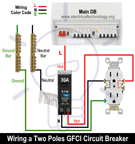
Wiring 15A – 240V Receptacle with GFCI
According to NEC 210.8, GFCI protection is required for receptacles installed in garages, basements, outdoors, laundry areas, and other wet or damp locations. Specifically, NEC 210.8(A)(1) through (A)(11) mandates that all outdoor receptacles must be installed downstream of GFCI protection, in accordance with Articles 426.28 and 427.22.
Currently, only 15A and 20A GFCI receptacles rated for 120V are available, typically in NEMA 5-15 and NEMA 5-20 configurations. For 240V outlets, GFCI protection must be provided using GFCI circuit breakers, as 240V GFCI receptacles are not available.
To wire a a 15A, 240V outlet in any location where GFCI protection is required by code, simply remove the standard 15A, 240V breaker and install a GFCI circuit breaker (2-pole, 15A, 240V) instead. The rest of the wiring remains the same as shown in the following wiring diagram.
Click image or open in a new tab to enlarge
FAQs:
How Many Amps Can a 15A – 240V Outlet Handle Safely?
A 15A–240V outlet is rated to handle 15 amperes of continuous load safely.
However, per NEC 210.19(A)(1), continuous loads should not exceed 80% of the circuit rating.
So, for continuous use (3 hours or more):
15A × 0.8 = 12A
- ✅ Safe continuous load: 12 amps
- ✅ Maximum non-continuous load: 15 amps
How Many Watts Can a 15A – 240V Receptacle Hold?
At 240 volts, a 15-amp outlet can handle non-continuous load of 3,600 watts (15A × 240V). For continuous use, limit the load to about 2,880 watts (80% of 36,00W).
Which Breaker Size is Suitable for a 15A – 240V Receptacle?
According to NEC 210.21(B)(2), the receptacle rating must not exceed the branch circuit rating.
Therefore, the correct size of breaker is 2-pole, 15A circuit breaker or GFCI for a 15A–240V outlet (NEMA 6-15R).
What is the Correct Wire Size and Cable Type to Use with a 15A – 240V Outlet?
Based on NEC Table – 310.16, Table – 210.24(1) & NEC 240.4(D)(4), the suitable wire size is 14 AWG copper (or #12 AWG aluminum) to use with a 15A outlet and circuit breaker. Similarly, for protection of a 15A circuit , the equipment grounding conductor (EGC) can be #14 AWG copper, as per NEC Table 250.122.
The cable type should be NM-B (Romex) for indoor & dry locations, UF-B for outdoor or underground runs and THHN/THWN conductors in conduit.
In simple words, based on the National Electrical Code (NEC), a 15-amp circuit should use #14 AWG copper or #12 AWG aluminum (minimum) for safe operation.
Can I Use a 15A Outlet on a 20A Circuit Breaker and Vice Versa?
- 15A outlet on 20A breaker: ✅ Allowed only if there are multiple 15A receptacles on the circuit (NEC 210.21(B)(3)). However, for a single 15A outlet, this is not allowed on a 20A breaker.
- 20A outlet on 15A breaker: ❌ Not allowed, as the outlet could allow connection of 20A devices, which would overload the 15A breaker.
Can I Use a 20A Outlet on a 15A Circuit and Vice Versa?
- 20A outlet on 15A circuit: ❌ Not permitted (violates NEC 210.21(B)(2)).
- 15A outlet on 20A circuit: ✅ Allowed only in multi-outlet branch circuits (e.g., more than one receptacle on the same circuit).
Can a 15A Device be Plugged into a 20A Outlet?
Yes – a 15A plug (NEMA 6-15P) can fit into a 20A receptacle (NEMA 6-20R) because the 6-20R design accommodates both 15A and 20A plugs. However, the circuit will still be protected by the 20A breaker.
Can a 20A Device be Plugged into a 15A Outlet?
NO – a 20A plug (NEMA 6-20P) has a different blade configuration that won’t fit into a 15A outlet (NEMA 6-15R).
This is a safety feature to prevent overloading a 15A circuit.
Can You Install a NEMA 6-15R in a 120V AC Circuit?
No – a NEMA 6-15R is designed for 240V only (two hot wires, no neutral). In other words, a 240V device must never be connected to a 120V outlet. For 120V applications, use NEMA 5-15R instead.
Instructions, Precautions & Codes
- A 15A load can be connected to a 20A outlet. It is permissible to use 15A receptacles if there are two or more receptacles (such as duplex) on a 20A circuit.
- It is against the code to connect 20A load on a 15A outlet. In addition, A 20A plug will not fit into a 15A receptacle, and attempting to force it in is dangerous.
- A standard 20-amp outlet accepts both 15-amp and 20-amp plugs (non-T-slot), but not vice versa.
- According to the NEC Table – 310.16 , 210.24.(1) and 240.4(D)(4), the correct Breaker and Wire size for a 15-Amp, 240V (6-15R) outlet is #14 AWG copper or #12 AWG Aluminum.
- Use #14/2 cable (hot wire, a neutral and one ground) for a 15A-240V breaker and receptacle/outlet.
- A 15A outlet can be used for a 12A continuous load and a maximum 15A non-continuous load (210.19(A)), 215.2, and 230.42(A).
- It is against the code to use a 15A outlet to draw 15A on a 10A breaker.
- It is against the code to use smaller gauge wire sizes (e.g., using 16, 18 AWG) instead of 14 AWG wire with a 15A outlet and breaker.
- 15A, 120V outlet can be installed on 15 amp breaker only.
Resources:
Related Wiring Tutorials
Related Wiring Tutorials
NEMA Family Outlets/Receptacle Wiring
NEMA 5 -Series
- How to Wire a 15A – 120V Outlet – NEMA 5-15 Receptacle
- How to Wire a 20A – 120V Outlet – NEMA 5-20 Receptacle
- How to Wire a 30A – 120V NEMA 5-30 Receptacle
- How to Wire a 50A – 120V – NEMA 5-50 Receptacle
NEMA 6-Series
- How to Wire a 15A – 240V Outlet – NEMA 6-15 Receptacle … (You are Here)
- How to Wire a 20A – 240V Outlet – NEMA 6-20 Receptacle
- How to Wire a 30A – 240V – NEMA 6-30 Receptacle
- How to Wire a 50A – 240V – NEMA 6-50 Receptacle
NEMA 10-Series
- How to Wire a 20A, NEMA 10-20 Non-Grounding Receptacle
- How to Wire a 30A, NEMA 10-30 Non-Grounding Receptacle
- How to Wire a 50A, NEMA 10-50 Non-Grounding Receptacle
NEMA 14-Series
- How to Wire a 20A – 125/250V NEMA 14-20 Receptacle
- How to Wire a 30A – 125/250V NEMA 14-30 Receptacle
- How to Wire a 50A – 125/250V NEMA 14-50 Receptacle
- How to Wire a 60A – 125/250V – NEMA 14-60 Receptacle
NEMA General Outlets/Receptacle
- How to Wire a 15A/125V, NEMA 1-15 Non-Grounding Outlet
- How to Wire a 20A/250V, NEMA 2-20 Non-Grounding Receptacle
- How to Wire a 30A – 125V, NEMA TT-30 Receptacle for RVs
- How to Wire a 3-Phase, 60A – 250V NEMA 15-60 Receptacle
- How to Wire a 3-Phase, 60A – 120/208V NEMA 18-60 Receptacle
Smart Devices Wiring Series
- How to Wire 120/240V Smart Load Center with Smart Breakers
- How to Wire a Smart Breaker in a Smart 120/240V Panel
- How to Wire a Smart GFCI Breaker in a 120/240V Smart Panel
- How to Wire Smart AFCI/GFCI Breaker in a Smart Load Center
- How to Wire a Smart Switch in a 120/240V Load Center
- How to Wire a 15A Wi-Fi Smart Outlet in a Smart Panel
- How to Wire 15A and 20A Wi-Fi Smart GFCI Outlets
General Wiring Installations:
- How to Size a Breaker and Wires in AWG with EGC for Load?
- How to Wire an Outlet Receptacle? Socket Outlet Wiring Diagrams
- How to a Wire 3-Way Combination Switch and Grounded Outlet?
- How to Wire Combo Switch and Outlet? – Switch/Outlet Combo Wiring Diagrams
- How to Wire 120V & 240V Main Panel? Breaker Box Installation
- How to Wire a Subpanel? Main Lug Installation for 120V/240V
- How to Wire 277V & 480V, 1-Phase & 3-Phase, Commercial Main Service Panel?
- How to Wire 240V Water Heater Thermostat – Non-Continuous?
- How to Wire 3-Phase Simultaneous Water Heater Thermostat?
- How to Wire Twin Timer for 120V/240V Circuits – ON/OFF Delay
- How to Wire ST01 Timer with Relay & Contactor for 120V/240V Motors?
- How to Wire Multifunction ON/OFF Delay Timer for 120V/240V Motors?
Switches Wiring
- How to Wire Single Pole, Single Throw (SPST) as 2-Way Switch?
- How to Wire Single Pole, Double Throw (SPDT) as 3-Way Switch?
- How to Wire Double Pole, Single Throw Switch? Wiring DPST
- How to Wire Double Pole, Double Throw Switch? Wiring DPDT
- How to Wire Double Switch? 2-Gang, 1-Way Switch – IEC & NEC
- How to Wire 4-Way Switch (NEC) or Intermediate Switch as 3-Way (IEC)?
GFCI/AFCI Breaker/Outlet Wiring
- How to Wire a GFCI Circuit Breaker?
- How to wire a GFCI Outlet?
- How to Wire GFCI Combo Switch and Outlet – GFCI Switch/Outlet
- How to Wire an AFCI Breaker?
- How to Wire an AFCI Outlet?
Related Posts:
- What is the Right Wire Size for 15A Breaker and Outlet?
- What is the Difference Between 15-Amp and 20-Amp Outlet?
- Difference Between Socket, Outlet and Receptacle
- Difference Between NEMA 14-50 Standard Vs EV Receptacle
- How to Find the Number of Outlets on a Single Circuit Breaker?
- How to Find Voltage & Ampere Rating of Switch, Plug, Outlet & Receptacle
- Can you use 15A Breaker on 20A Circuit and Vice Versa?
- Can You use a 15A Outlet on a 20A Circuit and Vice Versa?
- Ground Terminal Up or Down: Which Way Should Outlets Face?
- What Do the Green Dot or Orange Triangle Outlets Mean?
- What Do the Different Colors of Electrical Outlets Indicate?
- Why are Outlets and Receptacles in Hospitals Upside Down?
- How to Size a Load Center, Panelboards and Distribution Board?
- How to Determine the Number of Circuit Breakers in a Panelboard?
- How to Find the Proper Size of Circuit Breaker? Breaker Size Calculator & Examples
- How to Find The Suitable Size of Cable & Wire for Electrical Wiring Installation?
- Why is the Neutral Prong or Slot Wider on a Plug or Outlet?
- What Will Happen If You Connect a Male-to-Male Plug Between Outlets


