How to Wire a Countdown Timer Switch – 15 Mins to 12Hrs
Installation of 15A/20A Countdown Timer Switches for Lighting, Fans, and Motors in Single and 3-Way Circuits with Adjustable Timing from 15 Minutes to 12 Hours
Countdown Timer Switch
A countdown timer switch is an automatic control device designed to operate a connected load for a preset period and then turn it off automatically when the selected time expires. It is commonly used with lighting fixtures, bathroom exhaust fans, heat lamps, pumps, and other electrical loads to improve convenience, safety, and energy efficiency.
Unlike a standard wall switch that requires manual operation, a countdown timer switch is used to select a desired operating duration using dedicated time-setting buttons. Once activated, the timer counts down and automatically disconnects power to the load. This way, the timer switches prevent lights, fans, or other equipment from being left running unnecessarily.
Modern electronic countdown timer switches are available in various rating (15A/20A and 1HP load) and timing ranges, from a few minutes to several hours. Additionally, they support single-pole, 3-way, or multi-location installations. These devices are widely used in residential and light commercial applications where automatic shutoff helps reduce energy consumption and extend equipment life.
Rating & Features
- Name: Countdown Timer Switch – Decora Series from DT115 to DT212
- Poles: Single-Pole, 3-Way & Multiway – With Neutral
- Voltage: 120V 1-Phase AC Supply – 60 Hz
- Current: 15A/20A
- Load: Motor Fan: ½ to 1 HP , LED/CFL: 600W, Incandescent/Halogen: 1800W, ELV/MLV: 1200VA, 9.8A to 16A Inductive and 15/20A Resistive Load.
- Time Delay: Mins: 2, 5, 10, 15, 30, 60. Hours: 1, 2, 4, 8, 12.
- Wire Size: #12 – #10AWG Copper
- Neutral Wire: Required (but not for some models)
- Termination: Wired Leads / (Side Wired – Screw Termination and Mounting for Smart Companion Switches “D00SR, DD0SR”)
Wiring a 15A Countdown Timer Switch for ½ HP Motor
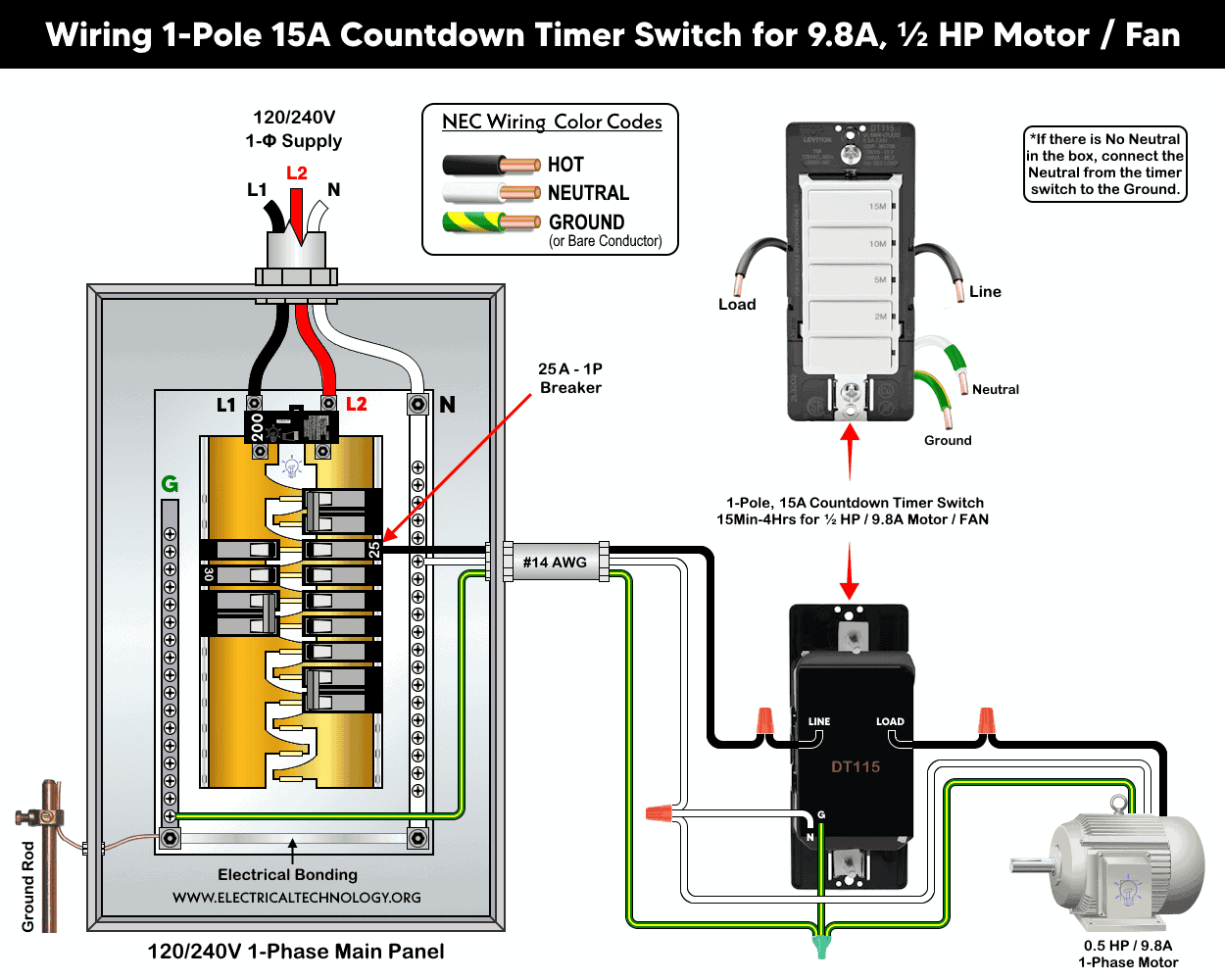
In the following wiring tutorial, we will show how to install a 15A countdown timer (Decora DT115) and control the 0.5 hp motor for preset time of 2 minutes up to 15 minutes. As shown in the wiring diagram, the countdown timer is wired through 14AWG branch circuit conductors and 1-pole, 25A, 120V circuit breaker in a 120/240V panel to a ½ hp motor.
Before installing a new switch or replacing an existing single-pole switch, make sure the power is completely disconnected at the circuit breaker or fuse.
As per the wiring diagram, connect the 4-built-in wires in the timer switch to the branch circuit conductors and load as follows:
- Connect the hot (black) wire from the circuit breaker to the LINE terminal.
- Connect the neutral (white) wire (if present in the box) from the panel to the N (Neutral) terminal of the timer and then continued to the load (motor).
- If there is no neutral in the box, connect the ground wire to the neutral terminal of the timer.
- Connect the equipment grounding conductor (bare copper or green wire) from the panel to the G (Ground) terminal.
- Connect the Load (switch’s built-in Black wire) to the the motor.
Click image or open in a new tab to enlarge
Wiring a 20A Countdown Timer Switch for 1 HP Motor
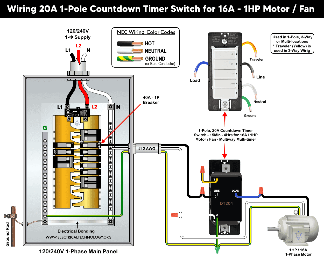
Similarly, the following wiring diagram shows the 20A countdown timer (Decora DT212) is wired through 12AWG branch circuit conductors and 1-pole, 40A, 120V circuit breaker in a 120/240V panel to a 1 hp motor.
As per the wiring diagram, the timer’s 5-built-in wires are connected to the branch circuit conductors and load as follows:
- The “LINE” wire of the timer is connected to the hot (black) conductor coming from the circuit breaker.
- The “N” wire of timer is connected to the neutral (white) conductor, which is also tied to the neutral terminal of the motor.
- The “G” wire of the timer is connected to the equipment grounding conductor (bare or green wire), which is also connected to the ground terminal of the motor.
- The “Load” wire (Blue) on the timer switch is connected to the motor (which is load side hot (line) conductor).
- The “T” terminal (switch’s built-in Yellow wire) is used for three-way/multi-way control (see the next section for 3-way wiring). In case of single load, cap the red wire with a wire connector (wire nut) and fix it safely inside the electrical box as an unused conductor.
Click image or open in a new tab to enlarge
Wiring Two Countdown Timer Switches for 3-Way Switching
If you want to control a connected load, such as a motor, from two different locations with automatic timed operation, you can install two identical countdown timers that support 3-way or multi-way control.
In this example, two Decora DT204 countdown timers are used to control a 1 HP motor, as shown in the wiring diagram.
- Connect the hot (line) conductor to the LINE wires of both timers.
- Connect the neutral and equipment grounding conductors (EGC) to the N and G wires of both timers, respectively, and also to the motor’s terminals.
- Interconnect the T (yellow) wires between the two countdown timers. These wires act as travelers for 3-way switching operation.
- Connect the LOAD (blue) wire of one timer to the motor’s line terminal. Leave the LOAD (blue) wire of the other timer unused and keep the factory-installed wire cap in place (i.e. do not remove the insulating label).
Click image or open in a new tab to enlarge
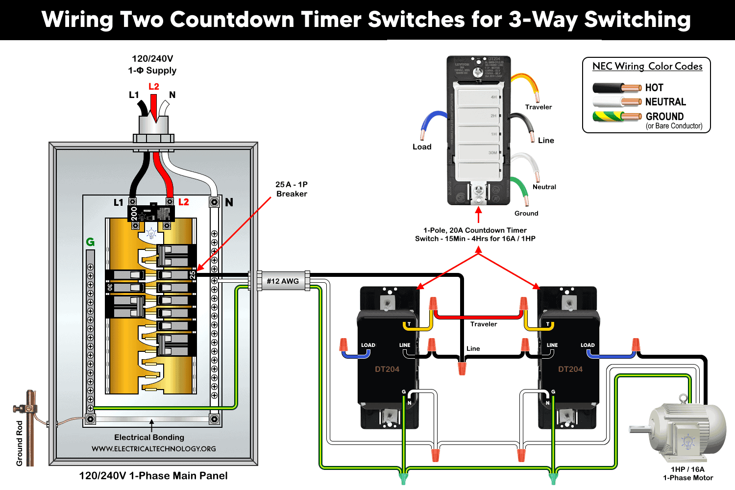
Once wired, the motor can be controlled from either location using the preset countdown intervals, such as 30 minutes, 1 hour, 2 hours, or 4 hours, after which the timer will automatically turn the motor OFF. For different time intervals, you may use other models (given above) which support the respective time period.
Installation of Countdown Timer with Smart Switch Companion for 3-Way Wiring
You can use a smart switch companion device with a countdown timer to control a motor from two different locations while maintaining automatic timed operation.
As shown in the wiring diagram below, a DT204 countdown timer is paired with a smart switch companion (DD0SR-DLZ with LED) to control a 1 HP motor.
In this wiring configuration, connect the branch-circuit conductors as follows:
- Line (Hot) Conductor: Connect to the LINE terminals of both the countdown timer and the companion switch. The connection between the “Line” terminals of both timer and switch companion acts as travelers 1.
- Neutral and Ground Conductors: Connect to the N and G terminals of the countdown timer, companion switch, and motor, respectively.
- Traveler Conductors 2: Interconnect the yellow and red traveler wires between the countdown timer and the companion switch for 3-way operation.
- Load Connection: Connect the LOAD (blue) wire from the countdown timer to the motor.
Click image or open in a new tab to enlarge
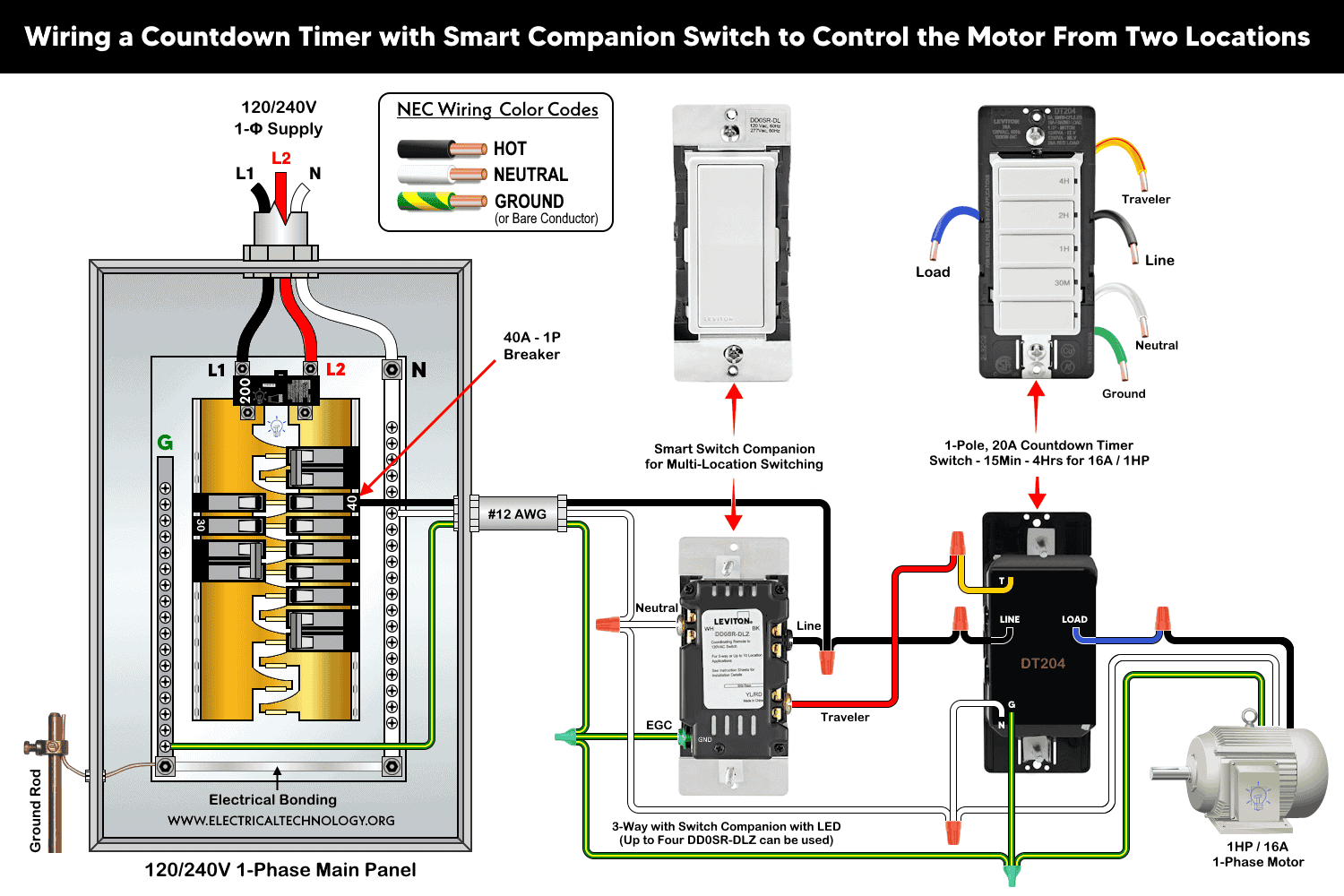
Once installed, the motor can be controlled from either location while still operating according to the selected countdown period.
This configuration can be expanded by adding up to four DD0SR smart switch companion devices. This way, the motor can be controlled from multiple locations while retaining the timer’s automatic shutoff functionality.
Installation of Countdown Timer with Smart Switch Companion for Multi-Way Wiring
The same objective i.e. controlling a motor from multiple locations with automatic timed operation can also be achieved using a countdown timer and other compatible smart switch companion devices.
In the following wiring diagram, a DT204 countdown timer is used together with a DD0SR-1Z Smart Switch Companion (without LED indicator). The wiring configuration is slightly different from the setup using the DD0SR-DLZ companion switch shown above.
The wiring is almost identical to the previous configuration, except that the line (hot) conductor from the circuit breaker is connected only to the LINE terminal of the countdown timer and is not connected to the DD0SR-1Z companion switch. In other words, the black and red screw terminals on the DD0SR-1Z companion switch are not used in this application.
Connect the circuit conductors as follows:
- Line (Hot): Connect only to the LINE terminal of the DT204 countdown timer.
- Neutral and Ground: Connect to the corresponding terminals of the countdown timer, companion switch, and motor.
- Travelers: Interconnect the traveler wires (Red and Yellow) between the countdown timer and the DD0SR-1Z companion switch as shown in the wiring diagram.
- Load: Connect the LOAD (blue) wire of the countdown timer to the motor.
Click image or open in a new tab to enlarge
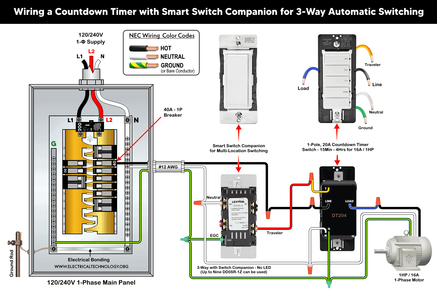
Once connected as per wiring diagram, the motor can be controlled from either location while still operating according to the selected countdown period.
For multi-location control, up to nine DD0SR-1Z smart switch companion devices may be added to the circuit which allows the motor to be controlled from multiple locations.
Operation and Setting
After installation, restore power and wait approximately 20 seconds for the timer to power up. During the power-up process, the bottom green LED blinks once every 5 seconds. Once initialization is complete, press any timer button to turn the load ON.
Each button is assigned a preset countdown duration. The green LED next to the selected button illuminates, and the load remains ON for the selected time period.
To select a different countdown time, press the button corresponding to the desired duration. The LED next to the newly selected button illuminates, and the load remains ON for the newly selected countdown period.
To turn the load OFF, press the OFF button (the bottom button), or wait until the selected countdown time expires. As time counts down, the LEDs turn OFF sequentially. It indicates the remaining time and the next lower preset level.
To override the countdown timer and keep the load ON continuously, press and hold the top button for more than 5 seconds. The LED will blink once per second to indicate that the timer is operating in the Extended ON mode. In this mode, the load remains ON for up to 24 hours before automatically turning OFF. To exit the Extended ON mode, press any timer button or the OFF button.
Preset Countdown Timer Values
The following table shows the values of preset time intervals for different models of countdown timer switches.
| Countdown Timer Switch | Countdown Timer Setting | ||||
| For 15A – 4 Wires Countdown Timers for Single Load | |||||
| Button 1 | Button 2 | Button 3 | Button 4 | Button 5 | |
| DT115 | 15 Minutes | 10 Minutes | 5 Minutes | 2 Minutes | OFF |
| DT130 | 30 Minutes | 15 Minutes | 10 Minutes | 5 Minutes | OFF |
| DT160 | 60 Minutes | 30 Minutes | 20 Minutes | 10 Minutes | OFF |
| DT102 | 2 Hours | 1 Hours | 30 Minutes | 15 Minutes | OFF |
| DT104 | 4 Hours | 2 Hours | 1 Hours | 30 Minutes | OFF |
| DT112 | 12 Hours | 8 Hours | 4 Hours | 2 Hours | |
| For 20A – 5 Wires Countdown Timers for Single Pole & 3-Way | |||||
| DT230 | 30 Minutes | 15 Minutes | 10 Minutes | 5 Minutes | OFF |
| DT260 | 60 Minutes | 30 Minutes | 20 Minutes | 10 Minutes | OFF |
| DT202 | 2 Hours | 1 Hour | 30 Minutes | 15 M Minutes | OFF |
| DT204 | 4 Hours | 2 Hours | 1 Hour | 30 Minutes | OFF |
| DT212 | 12 Hours | 8 Hours | 4 Hour | 2 Hours | OFF |
Disclaimer:
- The author will not be liable for any losses, injuries, or damages from the display or use of this information or if you try any circuit in wrong format. So please! Be careful because it’s all about electricity and electricity is too dangerous. If you are unsure, contact a licensed electrician to do it according to the local area codes.
Resources:
Smart Devices Wiring Series
- How to Wire a Smart Switch in a 120/240V Load Center
- How to Wire 120/240V Smart Load Center with Smart Breakers
- How to Wire a Smart Breaker in a Smart 120/240V Panel
- How to Wire a Smart GFCI Breaker in a 120/240V Smart Panel
- How to Wire Smart AFCI/GFCI Breaker in a Smart Load Center
- How to Wire a 15A Wi-Fi Smart Outlet in a Smart Panel
- How to Wire 15A and 20A Wi-Fi Smart GFCI Outlets
- How to Wire Z-Wave Smart Switch, Dimmer & Fan Speed Controller
- How to Wire a Digital and Wi-Fi Smart LED Dimmer Switch
- How to Wire a Smart Switch Companion with a Smart Switch
- Wiring a Smart Dimmer Switch Companion with a Digital Dimmer
- How to Install a Wire-Free Smart Dimmer Anywhere Companion
- How to Wire Smart Scene Controller Switch
- How to Install a Wireless Smart Scene Switch
- How to Install a Wake and Sleep Wireless Smart Switch
- How to Wire a Smart Motion Sensing Dimmer Switch
- How to Wire a Combo Humidity Sensor & Fan Control with Light Switch
- How to Wire Humidity Sensor and Fan Control Switch
Wiring Standard GFCI & Breakers
- How to Wire a 1-Pole Breaker
- How to Wire a 2-Pole Breaker
- How to Wire a 3-Pole Breaker
- How to Wire a 1-Pole GFCI
- How to Wire a 2-Pole GFCI
- How to Wire a 3-Phase, 3-Pole GFCI
- How to Wire a Tandem Breaker
- How to Wire GFCI Circuit Breakers
- How to Wire an AFCI Breaker
Wiring General Outlets & GFCI/AFCI Receptacles
- How to Wire an Outlet Receptacle? Socket Outlet Wiring Diagrams
- How to wire a GFCI Outlet?
- How to Wire an AFCI Outlet?
- How to a Wire 3-Way Combination Switch and Grounded Outlet?
- How to Wire a 15A – 125V Outlet – NEMA 5-15 Receptacle
- How to Wire a 20A – 125V Outlet – NEMA 5-20 Receptacle
- How to Wire a 15A – 250V Outlet – NEMA 6-15 Receptacle
- How to Wire a 20A – 250V Outlet – NEMA 6-20 Receptacle
- How to Wire a 50A – 125/250V Outlet – NEMA 14-50 Receptacle
Switches Wiring
- How to Wire Single Pole, Single Throw (SPST) as 2-Way Switch?
- How to Wire Single Pole, Double Throw (SPDT) as 3-Way Switch?
- How to Wire Double Pole, Single Throw Switch? Wiring DPST
- How to Wire Double Pole, Double Throw Switch? Wiring DPDT
- How to Wire Double Switch? 2-Gang, 1-Way Switch – IEC & NEC
- How to Wire 4-Way Switch (NEC) or Intermediate Switch as 3-Way (IEC)?
- How to Wire Auto & Manual Changeover & Transfer Switch – (1 & 3 Phase)
Sizing Breakers, Wires & Panels
- How to Size a Load Center, Panelboards and Distribution Board?
- How to Determine the Right Size Capacity of a Subpanel?
- How to Find the Right Wire Size for 100A Service 120V/240V Panel?
- How to Size a Circuit Breaker?
- How to Find the Proper Size of Wire & Cable In Metric & Imperial Systems
- How to Size a Breaker and Wires in AWG with EGC for Load?
- How to Size Service-Entrance Conductors and Feeder Cables?
- How to Size Feeder Conductors with Overcurrent Protection
- How to Size a Branch Circuit Conductors with Protection?
- How to Size Equipment Grounding Conductor (EGC)?
- How to Size Grounding Electrode Conductor (GEC)?
- How to Size Main Bonding Jumper (MBJ)?
- How to Size Motors FLC, HP, Voltage, Breaker Size and Wire Size
- What is the Correct Wire Size for 100A Breaker and Load?
- What is the Right Wire Size for 15A Breaker and Outlet?
- What is the Suitable Wire Size for 20A Breaker and Outlet?
Finding the Number of Breakers/Outlets in a Circuit
- How to Determine the Number of Circuit Breakers in a Panelboard?
- How to Find the Number of Outlets on a Single Circuit Breaker?
- How to Find Voltage & Ampere Rating of Switch, Plug, Outlet & Receptacle
- How to Calculate the Number of Fluorescent Lamps in a Final Sub Circuit?
- How to Calculate the Number of Incandescent Lamps in a Final Sub Circuit?
- How to Determine the Number of Lighting Branch Circuits?
- How to Determine the Number of Branch Circuits? – 3 Ways
- How to Find the Number of Lights on a Single Circuit Breaker?