How to Wire Smart Electric Vehicle Charging Station – 32A/80A
Wiring Level 2 EV Charging Stations Using Hardwired and Plug-In Connections – 32A to 80A
Leviton’s Electric Vehicle Charging Stations
The Leviton EV Series Electric Vehicle Charging Stations are Level 2 EV chargers designed for residential and commercial electric vehicle charging applications. Depending on the model, these chargers support charging currents ranging from 32A to 80A and require branch circuit breaker ratings from 40A to 100A at 240V for both hardwired and plug-in installations.
The chargers feature a built-in J1772 connector, making them compatible with most electric vehicles. Tesla vehicles can also be charged by using a compatible NACS (Tesla) adapter.
With high-speed Level 2 AC charging capability, the EV Series chargers can provide up to 76 miles of driving range per hour of charging when configured for 80A operation.
The charging station can be installed either as a permanent hardwired connection or as a plug-in unit using a NEMA 14-50 receptacle. In addition, select models support smart features through the Charging Station Management Software (AmpUp) platform and can be remotely monitored and controlled using the My Leviton smartphone app. Furthermore, the charger’s operation can be enabled and managed using RFID cards.
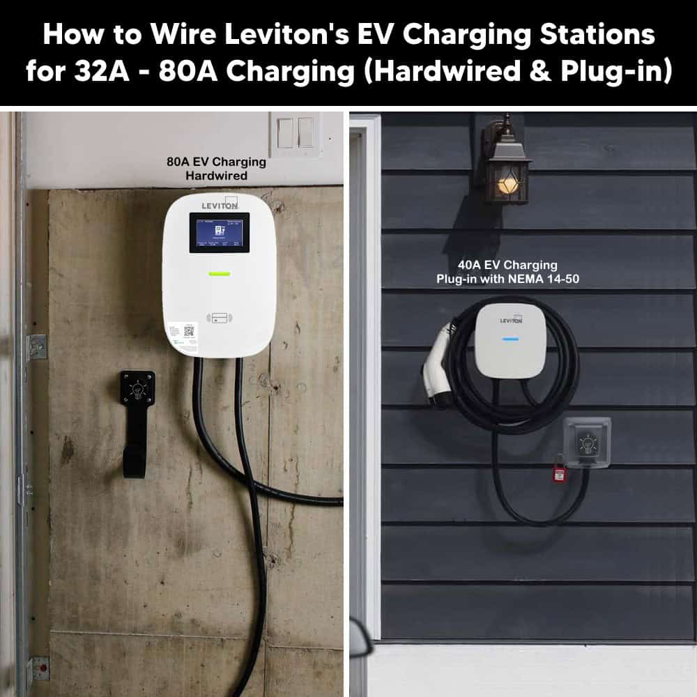
The available models, with variant and features are as follows:
| Model | Version / Variant | Features |
| EV320 | Standard version | Standard features |
| EV32W | Smart version | Works with App |
| EV40P | Smart version | Works with App |
| EV480 | Standard version | Standard features |
| EV48G | Commercial version | Without LCD screen |
| EV48S (U.S.) | Commercial version | With LCD screen and Management Software |
| EV48S-F (Canada) | Commercial version | With LCD screen and Management Software |
| EV48W | Smart version | Without LCD screen and works with App |
| EV48S-DP | Dual Port version | With LCD screen and Management Software |
| EV800 | Standard version | Standard features |
| EV80G | Commercial version | With Management Software |
| EV80S | Commercial version | With LCD screen and Management Software |
| EV80S-F (Canada) | Commercial version | With LCD screen and Management Software |
| EV80W | Smart version | Without LCD screen and works with App |
Although the charger comes with a built-in J1772 connector, which is the standard universal connector for EV charging, a NACS adapter (sold separately) can be used to charge Tesla vehicles. Therefore, the charger can be used to charge all types of electric vehicles.
Electrical Ratings & Specifications
- Name: Electric Vehicle Charging Station – Leviton’s EV Series
- Voltage: 208-240V AC – 60 Hz – Single-Phase
- Breaker Rating: 40A to 100A
- Charging Current: 32A, 40A, 48A, 80A – Adjustable from 16-40 in EV40P.
- Output Power: Min 7.6kW at 32A – 240V. Max 19.2kW at 80A – 240V
- Charging Speed (est Max.): up to ~76 miles of range per hour at 80A
- GFCI / RCD: 20 mA CCID per UL 2231
- Wire Size: (Hardwire) = #6 to #3 AWG copper
- Connector Type: SAE J1772 (Universal) or SAE J3400 – NACS Adapter (Tesla-style)
- Charging Cable: 18 – 25ft (5.5 m – 7.6 m) Cable
- Input Cable: 3 ft ( 1 m) to NEMA 14-50P plug
- Connectivity: 2.4 GHz Wi-Fi (802.11 a/b/g/n) Wi-Fi and Bluetooth – Pair with the My Leviton app & compatible with Samsung Smartthings, RFID authentication and Charging Station Management Software (AmpUp)
- Listed: UL 2594, 2231-1, 2231-2, 2251, 62, 991, 1998, 840. NFPA 70 (NEC) Article 625 & CSA compliant with cUL listed.
- Wiring Method: Hardwired, or Plug-in via NEMA 14-50 or NEMA 6-50 Plugs & Receptacles via L1 (Hot 1), L2 (Hot 2) and Ground (EGC).
- Mounting: Wall mount or pedestal mount
- Enclosure: UL / NEMA Type 3R rated for Indoor / Outdoor Mounting
Circuit Rating, Max Load & Charging Range
The breaker/circuit rating determines the maximum amperage the charger can be used for (different models). Per NEC continuous-load rules (NEC -210.19(A)(1), the EV charger must be set so its load never exceeds 80% of the circuit breaker’s rating. In other words, the breaker must be rated at no less than 125% of the charger’s continuous load).
The following table shows the breaker size, charging current, output power and estimated charging range per hour at 240V AC supply for different models.
| Model | Breaker Size | Charging Current | Output Power | Est. Range/Hour |
| EV32 | 40A | 32A | 7.6 kW | 31 mi / 50 km |
| EV40 | 50A | 40A | 9.6 kW | 39 mi / 62 km |
| EV48 | 60A | 48A | 11.5 kW | 47 mi / 75 km |
| EV80 | 100A | 80A | 19.2 kW | 76 mi / 122 km |
The Leviton’s EV Series charging stations can be wired and installed using two methods in indoor or outdoor locations:
- Hardwired Installation (Direct Connection)
- Plug-in Installation using a NEMA 14-50 Receptacle
Method 1 – Hardwire Installation
Hardwiring provides the most secure installation and allows higher charging currents. Hardwired installation is recommended for permanent installations and to avoid nuisance tripping of GFCI/RCD (mostly occurs in plug-in installations).
- Turn off power at the main and circuit breaker/fuse feeding the charger circuit. Verify with a voltmeter that the circuit is de-energized before touching any conductors.
- Install a a properly sized branch circuit breaker based on the model and charging current (Table is given above). For instance, use #3 AWG copper for 80A charging supplied by a 100A breaker.
- Select a mounting height location (up to 2-4 ft (24″ to 48″) above finished floor) where the charging cable can easily reach the vehicle’s port with slack.
- Using the wall-mounted bracket as a template (or the supplied mounting drill points), mark four screw-hole locations on the wall. Drill four holes of 0.35 in. (8.5 mm) in diameter / 2.05 in. (52 mm) in depth and insert wall anchors. Align the bracket’s screw holes with the wall holes. Insert the four M6 hexagonal expansion screws and tighten to secure the bracket. Use a level to confirm it is plumb.
- Route the incoming branch-circuit conductors (L1 (as Hot 1), L2 (as Hot 2), and ground (EGC) into the charger’s rear wiring compartment through the designated knockout. No neutral conductor is required in this configuration.
- Strip conductors to the appropriate length and land them on the charger’s terminal block: i.e. Black on L1, Red on L2, and Green or bare conductor on PE (ground terminal). Torque connections to the value specified inside the enclosure cover.
- Align the rear notch of the charger with the wall-mounted bracket and hang the unit on the bracket. Now, secure the charger to the bracket using the two M5 anti-theft/teeth screws provided.
- Restore power by turning ON the associated branch circuit breaker. Power on the unit and confirm the LED indicator shows a steady BLUE (Standby/Ready) light. (See the LED status indication table given in the below section 6 & 7).
Click image or open in a new tab to enlarge
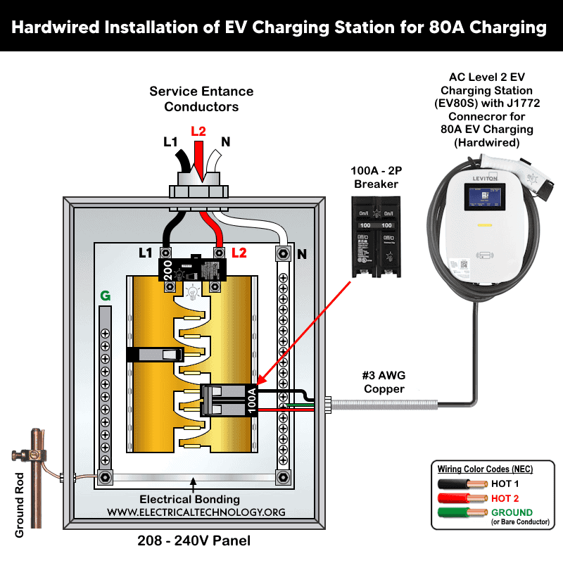
The EV Series charger supports 208V Wye systems. In the three-phase panel, connect either L1-L2, L2-L3 or L1-L3 with ground (do not connect Neutral). In other words, only two phases (lines) are used and the third (phase or line) remains unused.
NEC Considerations for Hardwired Installs
- NEC 625.54 (Personnel GFCI Protection): GFCI protection is required for EV charging receptacles. Hardwired EV chargers generally do not require upstream GFCI protection unless specified by the manufacturer. Current Leviton’s EV series charger models include an internal CCID (Charge Circuit Interrupting Device) for personnel protection.
- NEC 625.42 (Continuous Load): Branch-circuit conductors and overcurrent protection must be sized at 125% of the charger’s maximum output rating.
- NEC 625.43 (Disconnecting Means): A readily accessible disconnect must be provided. The branch circuit breaker may serve as the disconnect if it is within sight of the charger. Equipment rated above 60A or 150V-to-ground requires a lockable disconnect.
- NEC 210.8 (Location-Based GFCI Protection): Receptacles installed in garages, outdoors, or other specified locations may require GFCI protection regardless of EV charging requirements. Both Articles 625 and 210.8 must be considered.
- NEC 625.56 (Wet Locations): Receptacles installed in wet locations must be protected by a weatherproof, in-use-rated enclosure.
Method 2 – Plug-In Installation (NEMA 14-50)
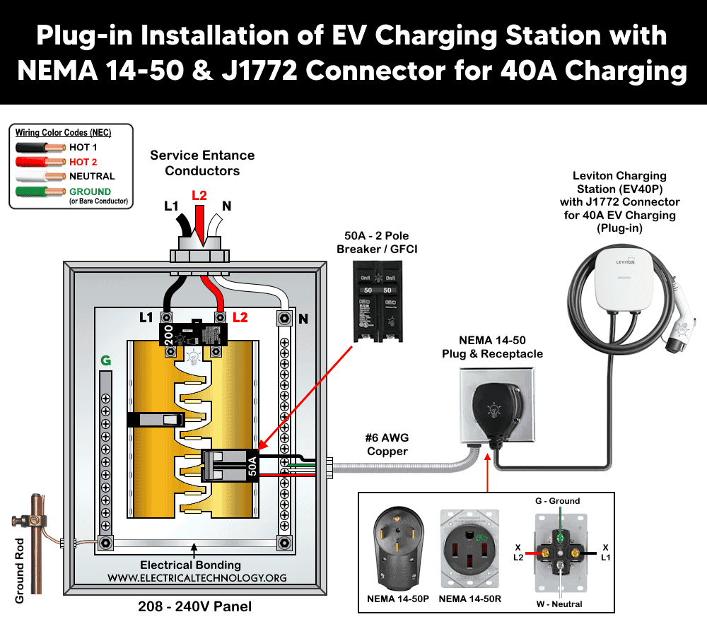
The NEMA 14-50R is a 3-pole, 4-wire, 125/250V, 50A receptacle used for electric ranges, RV pedestals and EV charging. It is installed upstream the charger where the 3ft input charger cable can reach easily. The two hot conductors connects to the two energized legs of a 240V (or 208V, 3-phase-derived) circuit protected by a 50A breaker. the EV series chargers itself do not use the neutral, but the 14-50 receptacle standard required the neutral connection with Ground.
To wire an industrial-grade NEMA 14-50 receptacle, connect the THHN/THWN-2, #6 AWG copper, four conductors (2 hots (L1, L2) + Neutral + Ground) from a 2-pole, 50A standard/GFCI breaker for 40/50A charging as follow:
- L1 i.e. Hot 1 (Black wire) to X (Brass screw)
- L2 i.e. Hot 2 (Red wire) to Y (Brass screw)
- Neutral (White wire) to W (Silver screw)
- Ground (Green/Bare wire) to G (Green screw)
For the rest of hardwired installation, follow the following steps:
- Turn off power at the main breaker
- Install a 240V single-phase 2-pole, 50A dedicated branch circuit breaker using #6 conductors (for 50A receptacle).
- Install the heavy duty / EV rated NEMA 14-50R receptacle within reach of the EV charge station 3ft input cord (18-48 inches above floor) as per terminal wiring given above.
- Select a mounting location for the charger that allows the 18-25 ft. output (charging) cable to comfortably reach the vehicle’s charging port, and keeps the 3 ft. input cable within reach of the installed NEMA 14-50 receptacle.
- Confirm the wall structure can anchor the bracket (2″ x 4″ stud) or solid wall is required.
- Mount the charger at a height between 2 ft. (600 mm) and 4 ft. (1200 mm) from the ground using M6 (anti-theft) screws. Now, tighten the screws to lock the charger onto the bracket.
Click image or open in a new tab to enlarge
Install Replacement Cord
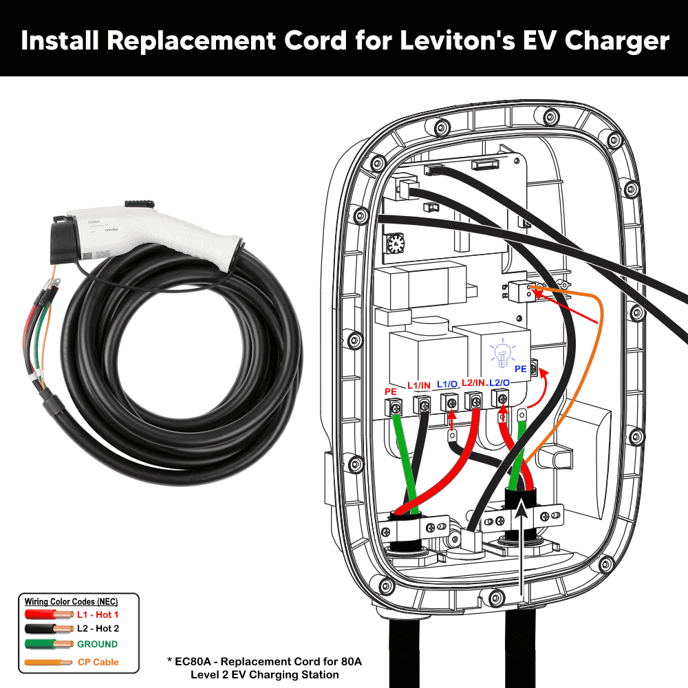
If you need to install a replacement charging cord (for example, the EC80A replacement 18-ft cord for an 80A Level 2 EV charging station with a J1772 charge connector), follow the instructions below:
- Remove the front and rear covers by loosening the 13 screws.
- Remove the three terminal screws and disconnect the cord terminal lugs from the circuit board. Then unplug the CP (Control Pilot) cable.
- Plug the orange-colored CP cable from the new replacement cord into the circuit board.
- Connect the black wire (L1/Hot 1) to the “L1/O” terminal.
- Connect the red wire (L2/Hot 2) to the “L2/O” terminal.
- Connect the green wire (Ground) to the “G/PE” grounding terminal.
- Tighten the terminal screws to a torque of 8.5–10.5 in-lb.
- Reinstall the front and rear covers.
To do so, connect the input wires as follows:
Click image or open in a new tab to enlarge
Charger Activation & Smart Control via App
If the charger model supports Charging Station Management Software, you can set up and activate the charger with AmpUp using the following steps:
- Visit the AmpUp activation page or scan the QR code on the green AmpUp sticker located on the charger.
- Select the charger brand and click Continue. Review the checklist, then click Get Started.
- Enter your name, email address, and phone number.
- Select an existing site or create a new one. For a new site, enter the installation address, host contact information, and the electrical panel capacity limit.
If the charger model supports Wi-Fi connectivity, the charger can be monitored and controlled remotely using a smartphone. The app allows users to view the charging station status, receive fault notifications, and manage various smart home devices, including EV charging, lighting controls, and smart load centers.
To do so, add the EV charger to the My Leviton app, and follow the on-screen instructions.
- Power ON your EV charger and place it into Setup Mode. When the charger is in Setup Mode, the blue LED indicator will flash.
- If the blue LED is not flashing, power cycle the charger and try again.
- Follow the instructions in the My Leviton app to add your charger and connect it to your Wi-Fi network.
To enable or disable RFID access control on your EV Series Smart Home Charger, open the My Leviton app and follow the path below:
Device → Settings → RFID Card
From this menu, you can enable or disable RFID authentication for your charger.
Status LED Lights
The LED indicator indicates the status of EV series chargers by Leviton (all models) as shown in the following table.
| Indicator | Status | Indication |
| Solid BLUE | Standby / Ready | Unit is powered and idle, waiting for a vehicle connection or user authorization. |
| Solid GREEN | Waiting for Charge | Vehicle connector is plugged into the vehicle inlet; charging has not yet started. |
| Flashing GREEN | Charging | Active charging session in progress. |
| Solid RED | Fault | An error has occurred – see Section 7, Error & Warning Messages. |
| Flashing BLUE | My Leviton Setup Mode | Wi-Fi provisioning mode (EV40P, EV32W, EV48W, EV80W). |
Fault Codes & Troubleshooting
The following table shows the error and warning message through the RED led indictor on the charger (EV48G / EV48S / EV80G / EV80S and other EV series charger) which can be used for maintenance and troubleshooting
| Status | Red LED Indicator | Remark |
| Emergency Fault | Constantly bright | Power cycle the unit |
| Input Over-Voltage (OVP) | 1 flash + 3-sec pause | Auto recover |
| Input Under-Voltage (UVP) | 2 flashes + 3-sec pause | Auto recover |
| Output Over-Current (OCP) | 3 flashes + 3-sec pause | Auto recover – unplug and reinsert connector |
| Over-Temperature (OTP) | 4 flashes + 3-sec pause | Auto recover |
| CCID / RCD Abnormal | 5 flashes + 3-sec pause | Auto recover – unplug and reinsert connector |
| Ground Fault | 6 flashes + 3-sec pause | Auto recover |
| Control Pilot Fault | 7 flashes + 3-sec pause (or blinking) | Auto recover – unplug and reinsert connector |
| Relay Fault | 8 flashes + 3-sec pause | Contact Electrician / Customer Service |
| CCID / RCD Self-Test Fault | 9 flashes + 3-sec pause (or Stable red) | Contact Electrician / Customer Service |
| Relay Self-Test Fault | 10 flashes + 3-sec pause | Contact Electrician / Customer Service |
| Meter Fault | Keeps blinking | Contact Electrician / Customer Service |
For faults marked “Auto Recover,” first unplug and firmly reinsert the vehicle connector before assuming a hardware failure.
Instruction and Precautions
- Disconnect the power supply and verify that the circuit is de-energized before beginning the installation.
- Ensure the installation complies with NEC Article 625 (Electric Vehicle Power Transfer System), as well as other applicable NEC requirements, including Articles 110, 210, 220, 240, and 310. Also comply with all applicable local electrical codes and the requirements of the Authority Having Jurisdiction (AHJ).
- In accordance with NEC Article 625, mount the EV connector holster between 18 in. (450 mm) and 4 ft (1.2 m) above the floor for indoor installations, and at least 24 in. (600 mm) above grade for outdoor installations.
- In areas prone to frequent lightning or thunderstorms, install a Surge Protective Device (SPD) at the service panel to help protect the EV charging station from transient voltage surges.
- Install the EV charging station in accordance with the National Electrical Code (NEC), the Canadian Electrical Code (CEC), and all applicable local codes and amendments governing Electric Vehicle Supply Equipment (EVSE). Consult your local electrical inspector or AHJ before beginning the installation if required.
- This equipment must be installed, adjusted, and serviced only by a qualified and licensed electrician who is familiar with EV charging equipment, applicable electrical codes, and the associated hazards.
- Failure to follow these instructions may result in electric shock, fire, serious personal injury, death, or damage to the equipment and property.
Disclaimer:
The author will not be liable for any losses, injuries, or damages from the display or use of this information or if you try any circuit in wrong format. So please! Be careful because it’s all about electricity and electricity is too dangerous. If you are unsure, contact a licensed electrician to do it according to the local area codes.
Resources:
EV Charger Wiring Series
- How to Wire AC Level 2 EV Smart Breaker Charger – 40A/32A
- How to Wire an EV Wall Charger – Hardwired and Plug-in
- How to Wire ChargePoint Home Flex Charger for Every EV
- How to Wire 48A Level 2 Dual Port EV Charging Station
- How to Wire and Use Tesla Gen 3 Mobile Connector Charger
- How to Wire a Tesla Wall Connector & Universal EV Charger
Smart Devices Wiring Series
- How to Wire a Smart Switch in a 120/240V Load Center
- How to Wire 120/240V Smart Load Center with Smart Breakers
- How to Wire a Smart Breaker in a Smart 120/240V Panel
- How to Wire a Smart GFCI Breaker in a 120/240V Smart Panel
- How to Wire Smart AFCI/GFCI Breaker in a Smart Load Center
- How to Wire a 15A Wi-Fi Smart Outlet in a Smart Panel
- How to Wire 15A and 20A Wi-Fi Smart GFCI Outlets
- How to Wire Z-Wave Smart Switch, Dimmer & Fan Speed Controller
- How to Wire a Digital and Wi-Fi Smart LED Dimmer Switch
- How to Wire a Smart Switch Companion with a Smart Switch
- Wiring a Smart Dimmer Switch Companion with a Digital Dimmer
- How to Install a Wire-Free Smart Dimmer Anywhere Companion
- How to Wire Smart Scene Controller Switch
- How to Install a Wireless Smart Scene Switch
- How to Install a Wake and Sleep Wireless Smart Switch
- How to Wire a Smart Motion Sensing Dimmer Switch
- How to Wire a Combo Humidity Sensor & Fan Control with Light Switch
- How to Wire Humidity Sensor and Fan Control Switch
- How to Wire a Countdown Timer Switch – 15 Mins to 12Hrs
Wiring Standard GFCI & Breakers
- How to Wire a 1-Pole Breaker
- How to Wire a 2-Pole Breaker
- How to Wire a 3-Pole Breaker
- How to Wire a 1-Pole GFCI
- How to Wire a 2-Pole GFCI
- How to Wire a 3-Phase, 3-Pole GFCI
- How to Wire a Tandem Breaker
- How to Wire GFCI Circuit Breakers
- How to Wire an AFCI Breaker
Main Panels Wiring Tutorials
- How to Wire 120V/240V Main Panel? Breaker Box Installation
- How to Wire 120/240V Smart Load Center with Smart Breakers
- How to Wire 208V/120V, 1-Phase & 3-Phase Main Panel?
- How to Wire 240V, 208V & 120V, 1 & 3-Phase, High Leg Delta Main Panel?
- How to Wire 277V/480V, 1-Phase & 3-Phase Main Service Panel?
- How to Wire a Subpanel? Main Lug Installation for 120V/240V
- Single Phase Electrical Wiring Installation in Home according to NEC & IEC
- Three Phase Electrical Wiring Installation in Home – NEC & IEC
- How To Wire a Single Phase kWh Meter – 120V/240V
- How to Wire a Three-Phase Meter? 120/208/240/277/347/480/600V
- How to Wire Spa Panel for Hot Tub using 2-P GFCI & Breaker
Wiring General Outlets & GFCI/AFCI Receptacles
- How to Wire an Outlet Receptacle? Socket Outlet Wiring Diagrams
- How to wire a GFCI Outlet?
- How to Wire an AFCI Outlet?
- How to a Wire 3-Way Combination Switch and Grounded Outlet?
- How to Wire a 15A – 125V Outlet – NEMA 5-15 Receptacle
- How to Wire a 20A – 125V Outlet – NEMA 5-20 Receptacle
- How to Wire a 15A – 250V Outlet – NEMA 6-15 Receptacle
- How to Wire a 20A – 250V Outlet – NEMA 6-20 Receptacle
- How to Wire a 30A – 250V, NEMA 6-30 Receptacle
- How to Wire a 50A – 125/250V Outlet – NEMA 14-50 Receptacle for EVs
Sizing Breakers, Wires & Panels
- How to Size a Load Center, Panelboards and Distribution Board?
- How to Determine the Right Size Capacity of a Subpanel?
- How to Find the Right Wire Size for 100A Service 120V/240V Panel?
- How to Size a Circuit Breaker?
- How to Find the Proper Size of Wire & Cable In Metric & Imperial Systems
- How to Size a Breaker and Wires in AWG with EGC for Load?
- How to Size Service-Entrance Conductors and Feeder Cables?
- How to Size Feeder Conductors with Overcurrent Protection
- How to Size a Branch Circuit Conductors with Protection?
- How to Size Equipment Grounding Conductor (EGC)?
- How to Size Grounding Electrode Conductor (GEC)?
- How to Size Main Bonding Jumper (MBJ)?
- How to Size Motors FLC, HP, Voltage, Breaker Size and Wire Size
- What is the Correct Wire Size for 100A Breaker and Load?
- What is the Right Wire Size for 15A Breaker and Outlet?
- What is the Suitable Wire Size for 20A Breaker and Outlet?