How to Install a Wake and Sleep Wireless Smart Switch
Wiring Installation of a Wake/Sleep Smart Wireless Switch for Light Control
In this smart devices installation series, we will discuss the adorne® Wake/Sleep Wireless Smart Switch with Netatmo by Legrand. This tutorial with wiring diagrams and instructions shows the hassle-free installation of a wireless smart switch to enable lighting control from different locations in just a few minutes.
What is Wake/Sleep Wireless Smart Switch
The Legrand Wake/Sleep wireless smart switch with Netatmo (WNAL43W1) is a modern lighting control device designed for simple and automated daily routines. Similar to other Smart devices (smart switches, dimmer, outlets), the Legrand adorne Wake/Sleep Wireless Smart Switch with Netatmo allow users to control multiple lights or scenes with a single touch. Instead of operating one light at a time, the switch activates preset “wake” or “sleep” lighting scenes for convenience and comfort.
It is a battery-powered, wire-free device that can be installed anywhere without cutting walls or running cables. This makes it highly flexible for locations such as bedrooms, bathrooms, hallways, or near a bedside. The switch communicates wirelessly with other smart devices through a dedicated system network, such as a smart gateway. These battery operated smart devices can be fixed in a box or mount anywhere on the wall.
The Wake/Sleep is a 1-gang wireless switch, which is part of a broader smart home ecosystem. It works with apps and voice assistants (Amazon Alexa, Google Assistant and Apple HomeKit) to manage lighting scenes, schedules, and automation. With one-touch control, users can turn on multiple lights in the morning or switch everything off at night. In short, it improves both energy efficiency and user convenience in advanced smart home automation systems.
Wiring a Wake/Sleep Wireless Smart Switch
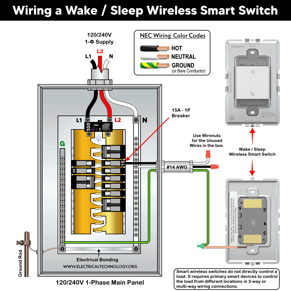
Installing a Wake/Sleep Wireless Smart Switch with Netatmo is significantly easier than traditional switch installation. There is no electrical wiring involved (i.e. it does not require line, load, or neutral wiring). Instead, it is a scene controller which communicates wirelessly with other smart devices through a Netatmo smart system. This makes it ideal for retrofit applications and smart home upgrades.
The process mainly involves pairing, mounting, and configuring scenes, rather than electrical connections. Once installed, it provides reliable one-touch control for daily routines like waking up and going to sleep.
Although no wiring is involved at all, always turn OFF power at the service panel to avoid electric shock (especially if installing in the box).
To wire a wireless wake/sleep smart switch, chose a suitable location based on the following installation methods.
Electrical Box Installation: Suitable for replacing or adding to an existing switch location.
Provides a more permanent and professional finish.
Wall Surface Installation: Ideal for adding control points anywhere without wiring.
Uses adhesive strips or screws depending on wall condition.
Installation in a One-Gang Electrical Box
Remove the ground wire label on the back of the device. Connect the ground wire to the box ground using the provided wire connector.
If installing alongside other Netatmo wired devices (such as WNAL10), follow their instructions for unused conductors. Mount the device into the electrical box using the supplied screws. Handle the unused conductors with care i.e. add wire nuts to the bare conductor and fix inside the box. Tighten screws just enough to secure. overtighten.
Click image or open in a new tab to enlarge
Multi-Gang Installation
For installations with multiple switches, replace the standard frame with an adorne multi-gang frame. Remove the device from its original frame by gently pushing and lifting it out. Attach it to the multi-gang frame using mounting screws.
Wall Surface Mounting (No Electrical Box)
Use the provided double-sided adhesive strips for smooth surfaces such as tiles. Align strips with the marked positions on the back of the device.
For rough or uneven walls, use drywall screws if mounting on a stud. Use wall anchors if no stud is present. Press firmly to secure the device.
After installation, snap the wall plate onto the frame. Adjust using the built-in three click-stop positions for proper alignment.
Paring, Powering and Setup
Remove the battery insulation tab to power the device. Download the Legrand Home + Control app from the App Store or Google Play and follow in-app instructions to:
- Connect the device to your home network
- Pair it with other Netatmo smart devices
- Use the app to configure Wake/Sleep scenes and control behavior.
For smart lighting control, follow this step-by-step guide for the Netatmo system to select your gateway, primary device, and add-on devices.
To enable Amazon Alexa, Google Home Voice Control Integration or or voice assistance to create scene for adorne & radiant® With Netatmo, follow this setup guide for automation.
LED indicators and controls indicates different states of the smart switch i.e.
- Blinking Green LED: Device is attempting to connect to the network
- EZ Button: Used for setup and configuration
To factory reset the devices, press and hold the EZ button for 7 seconds. Release when LED blinks red. The LED turns off once reset is complete.
Instructions & Precautions
- Make sure to disconnect the power supply by switching OFF the breaker in the main panel before doing any electrical work.
- The wire length from smart switch to other companion device should not exceed 300 ft (90 meters).
- Smart devices are only suitable for indoor use, and should not be used for medical applications.
Disclaimer:
- The author will not be liable for any losses, injuries, or damages from the display or use of this information or if you try any circuit in wrong format. So please! Be careful because it’s all about electricity and electricity is too dangerous. If you are unsure, contact a licensed electrician to do it according to the local area codes.
Resources:
Smart Devices Wiring Series
- How to Wire a Smart Switch in a 120/240V Load Center
- How to Wire 120/240V Smart Load Center with Smart Breakers
- How to Wire a Smart Breaker in a Smart 120/240V Panel
- How to Wire a Smart GFCI Breaker in a 120/240V Smart Panel
- How to Wire Smart AFCI/GFCI Breaker in a Smart Load Center
- How to Wire a 15A Wi-Fi Smart Outlet in a Smart Panel
- How to Wire 15A and 20A Wi-Fi Smart GFCI Outlets
- How to Wire Z-Wave Smart Switch, Dimmer & Fan Speed Controller
- How to Wire a Digital and Wi-Fi Smart LED Dimmer Switch
- How to Wire a Smart Switch Companion with a Smart Switch
- Wiring a Smart Dimmer Switch Companion with a Digital Dimmer
- How to Install a Wire-Free Smart Dimmer Anywhere Companion
- How to Wire Smart Scene Controller Switch
- How to Install a Wireless Smart Scene Switch
- How to Wire a Smart Motion Sensing Dimmer Switch
Wiring Standard GFCI & Breakers
- How to Wire a 1-Pole Breaker
- How to Wire a 2-Pole Breaker
- How to Wire a 3-Pole Breaker
- How to Wire a 1-Pole GFCI
- How to Wire a 2-Pole GFCI
- How to Wire a 3-Phase, 3-Pole GFCI
- How to Wire a Tandem Breaker
- How to Wire GFCI Circuit Breakers
- How to Wire an AFCI Breaker
Wiring General Outlets & GFCI/AFCI Receptacles
- How to Wire an Outlet Receptacle? Socket Outlet Wiring Diagrams
- How to wire a GFCI Outlet?
- How to Wire an AFCI Outlet?
- How to a Wire 3-Way Combination Switch and Grounded Outlet?
- How to Wire a 15A – 125V Outlet – NEMA 5-15 Receptacle
- How to Wire a 20A – 125V Outlet – NEMA 5-20 Receptacle
- How to Wire a 15A – 250V Outlet – NEMA 6-15 Receptacle
- How to Wire a 20A – 250V Outlet – NEMA 6-20 Receptacle
- How to Wire a 50A – 125/250V Outlet – NEMA 14-50 Receptacle
Switches Wiring
- How to Wire Single Pole, Single Throw (SPST) as 2-Way Switch?
- How to Wire Single Pole, Double Throw (SPDT) as 3-Way Switch?
- How to Wire Double Pole, Single Throw Switch? Wiring DPST
- How to Wire Double Pole, Double Throw Switch? Wiring DPDT
- How to Wire Double Switch? 2-Gang, 1-Way Switch – IEC & NEC
- How to Wire 4-Way Switch (NEC) or Intermediate Switch as 3-Way (IEC)?
- How to Wire Auto & Manual Changeover & Transfer Switch – (1 & 3 Phase)
Sizing Breakers, Wires & Panels
- How to Size a Load Center, Panelboards and Distribution Board?
- How to Determine the Right Size Capacity of a Subpanel?
- How to Find the Right Wire Size for 100A Service 120V/240V Panel?
- How to Size a Circuit Breaker?
- How to Find the Proper Size of Wire & Cable In Metric & Imperial Systems
- How to Size a Breaker and Wires in AWG with EGC for Load?
- How to Size Service-Entrance Conductors and Feeder Cables?
- How to Size Feeder Conductors with Overcurrent Protection
- How to Size a Branch Circuit Conductors with Protection?
- How to Size Equipment Grounding Conductor (EGC)?
- How to Size Grounding Electrode Conductor (GEC)?
- How to Size Main Bonding Jumper (MBJ)?
- How to Size Motors FLC, HP, Voltage, Breaker Size and Wire Size
- What is the Correct Wire Size for 100A Breaker and Load?
- What is the Right Wire Size for 15A Breaker and Outlet?
- What is the Suitable Wire Size for 20A Breaker and Outlet?
Finding the Number of Breakers/Outlets in a Circuit
- How to Determine the Number of Circuit Breakers in a Panelboard?
- How to Find the Number of Outlets on a Single Circuit Breaker?
- How to Find Voltage & Ampere Rating of Switch, Plug, Outlet & Receptacle
- How to Calculate the Number of Fluorescent Lamps in a Final Sub Circuit?
- How to Calculate the Number of Incandescent Lamps in a Final Sub Circuit?
- How to Determine the Number of Lighting Branch Circuits?
- How to Determine the Number of Branch Circuits? – 3 Ways
- How to Find the Number of Lights on a Single Circuit Breaker?