How to Wire 120/240V Smart Load Center with Smart Breakers
Wiring Installation of 120/240V, 1-Phase Smart Breakers in a Smart Electric Panel
In the era of rapidly evolving technology, conventional panel boards and breaker boxes are no longer sufficient for modern smart home automation. Instead, newly designed smart load centers are emerging to enhance residential energy management, allowing homeowners to control their entire electrical system through a smartphone.
In the following wiring tutorial, we will demonstrate how to install a new smart load center or upgrade an existing standard load center to a smart load center. This upgrade enhances convenience, whether you are at home or away. With a smart load center, you can remotely monitor and control your home’s electrical system, including turning breakers ON and OFF, scheduling operations, tracking energy usage history, optimizing power consumption, and ultimately reducing electricity costs.
What is a Smart Load Center?
A smart load center is the next-generation residential electrical panel that combines traditional load distribution with advanced digital control, energy monitoring, and remote management capabilities. At its core, it functions like a conventional load center to safely distribute power to branch circuits, but adds connectivity through remote control via smartphone using Wi-Fi to control and manage smart circuit breakers.
Click image or open in a new tab to enlarge
This transforms the electrical panel from a passive distribution point into an interactive energy management platform, giving homeowners deeper visibility and control over their home’s electrical usage.
How it Works?
A smart panel board integrates traditional circuit breaker functionality with digital monitoring, remote control, and intelligent automation. In the Leviton ecosystem, 2nd Gen smart breakers communicate with a smart hub and the My Leviton app to report real-time energy data, send alerts, and allow remote ON/OFF control of individual circuits.
These systems also support anomaly detection which notifies users if a load behaves abnormally (e.g., long run times or no draw when expected) and can monitor whole-home energy use, including from grid and alternate sources like solar, batteries, wind or backup generators using automatic transfer switch (ATS), which eliminates the need of costly secondary panels and subpanels.
How It Differs from a Standard Panel
Unlike a standard panel, which simply houses mechanical circuit breakers with no connectivity or remote visibility, smart load centers provide digital insights and control. Standard panels cannot report energy usage, send automated alerts, or enable remote switching of breakers.
Smart load centers accomplish this by combining advanced breakers with a communication hub, Wi-Fi connectivity, and a mobile app interface, enabling homeowners to view historical trends, receive diagnostics, and manage circuits from anywhere. In contrast, standard panels only allow on-site manual breaker operation and require no network or app.
Advantages and Features
Smart load centers offer several distinct advantages over standard electrical panels:
- Remote Control & Scheduling: Turn circuits ON/OFF or schedule their operation via the My Leviton app on a smartphone or tablet.
- Faster Installation & Upgrade Path: The modular, fully plug-on breaker system allows mixing standard and smart breakers, enabling cost-effective upgrades over time.
- Real-Time & Historical Energy Monitoring: Track whole-home and individual circuit consumption by day, week, month or year, and estimate energy costs.
- Smart Anomaly Detection: Automatic alerts for unusual electrical activity, like a freezer not running or extended heavy loads.
- Flexible Integration with Backup Power: Designate essential and nonessential circuits and shed noncritical loads automatically when a backup generator is active (with compatible hardware).
Electrical Specifications and Ratings:
- Busbar Amp Rating: 100 to 225A
- Voltage: 120/240V – Single-Phase AC Supply – 60 Hz
- Busbar Material: Copper, Bright Tin-Plated
- Breakers Rating: 15A to 60A from branch circuit breakers and 100A to 225A for main breakers
- Spaces: 20, 30, 42 & 66
- Supply Lines: 3 AWG – 300 MCM Cu/Al
- Main Lug & Neutral Line: 6 AWG – 300 MCM Cu/Al
- Ground: 4 AWG – 2/0 AWG Cu/Al
- NEMA Rating: NEMA 1 – Indoor and NEMA 3 – Outdoor
- Mounting: Surface Mounting and Flush Mounting
- Compatibility: LDATA hub e.g. Leviton Whole Home Energy Monitor (LWHEM-2) Hub, LSMMA, LSBMA and smart devices by Leviton e.g. standard thermal breakers, GFCI, AFCI, surge protection, dual-function protection (GFCI/AFCI) and GFPE.
Wiring 120/240V Smart Load Center & Breakers
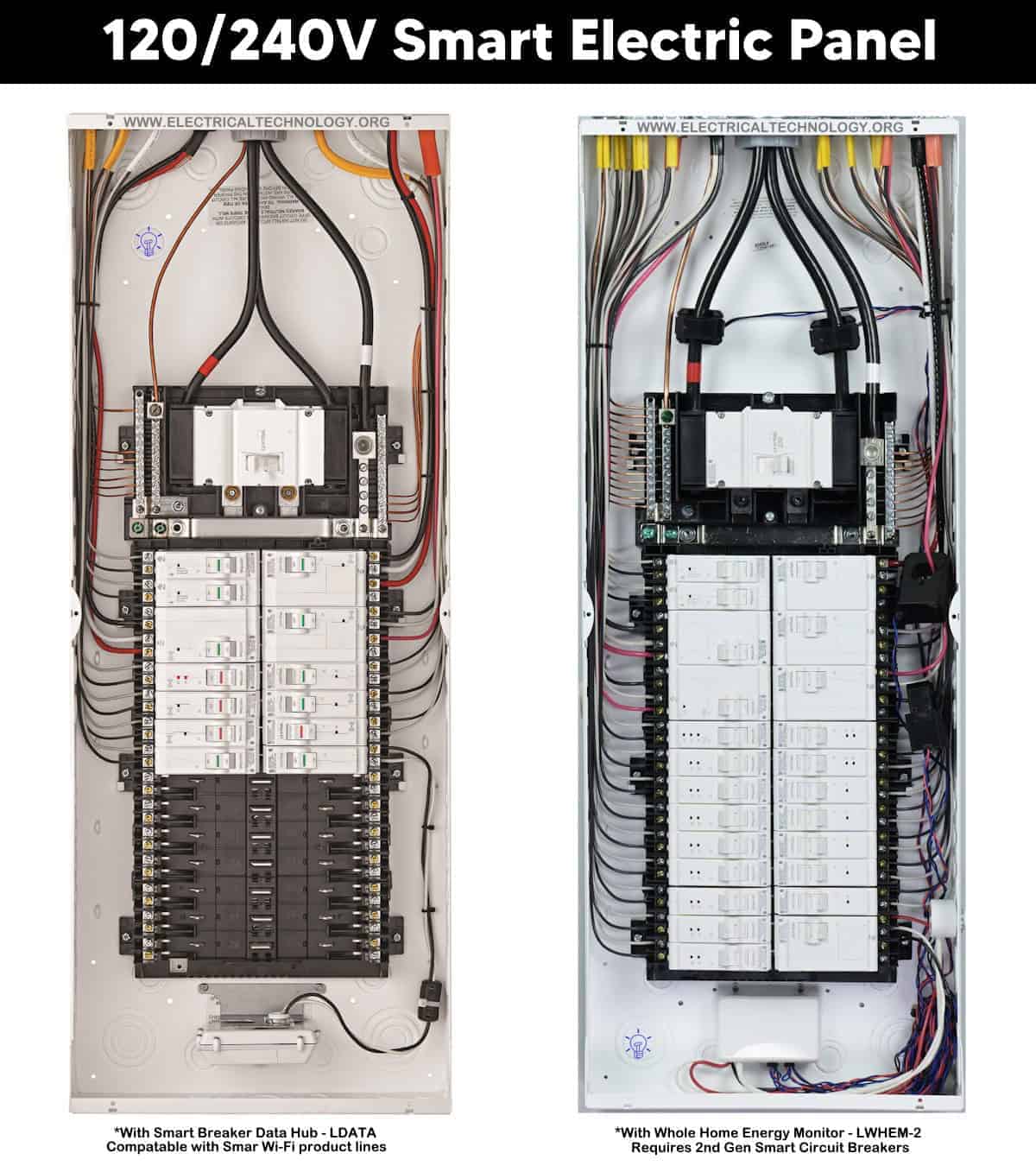
The internal construction of a 120/240V smart load center by Leviton (LP220-BPD) is similar to that of a standard 120/240V panel, except that a neutral connection is provided on both sides adjacent to the hot busbars for each plug-on breaker. As a result, there is no need to install pigtails from AFCI/GFCI, or 2-pole 240V breakers to the main neutral busbar.
As shown in the following figure, the 200A main breaker feeds the two hot busbars. The main neutral and equipment grounding busbars are located on the right and left sides of the panel.
Power Distribution
Power distribution in a smart load center is the same as in a traditional 120/240V single-phase panel:
- Voltage between Hot 1 and Neutral = 120V (1 – Phase)
- Voltage between Hot 2 and Neutral = 120V (1 – Phase)
- Voltage between Hot 1 and Hot 2 = 240V (1 – Phase)
- Voltage between Neutral and Ground = 0V
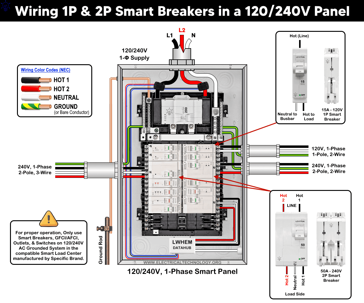
1-Pole, 2-Wire 120V Circuits
As illustrated, the first 2nd-generation 1-pole smart breaker (top right side) is connected to the Hot 1 and Neutral busbars. It is used to protect a 120V circuit (for example, a NEMA 5-15 outlet).
The circuit conductors are:
- Hot 1 (Black)
- Neutral (White)
- Equipment Ground (Bare copper or Green with yellow stripe)
Important: The neutral conductor must be connected from the breaker’s neutral terminal to the load. It must not be connected from the main neutral busbar in the panel.
2-Pole, 2-Wire 240V Circuits
Similarly, the second 2-pole smart breaker in the same column is connected to Hot 1 and Hot 2 (and internally interfaces with the neutral bus for monitoring, if applicable). It is used to protect a 240V circuit that does not require a neutral conductor (for example, a NEMA 6-20 outlet).
The circuit conductors are:
- Hot 1 (Black)
- Hot 2 (Red)
- Equipment Ground (Bare copper or Green with yellow stripe)
In this configuration, no neutral conductor is required for the load.
2-Pole, 3-Wire 240V Circuits
The third 2-pole smart breaker (left side) is connected to Hot 1, Hot 2, and the Neutral busbars. It is used to protect a 120/240V circuit (for example, a NEMA 14-50 receptacle).
The circuit conductors are:
- Hot 1 (Black)
- Hot 2 (Red)
- Neutral (White)
- Equipment Ground (Bare copper or Green with yellow stripe)
The neutral conductor to the load must be connected from the breaker’s neutral terminal, not from the main neutral busbar inside the panel.
To make the smart wiring system even smartest, Install the Leviton Whole Home Energy Monitor (LWHEM) (as shown in the fig using a standard 1-pole breaker for LDATA hub or a non-smart standard 2-pole breaker for LWHEM-2), snap the 2nd generation smart breakers for load, add load center and enroll breakers in the My Leviton App.
Click image or open in a new tab to enlarge
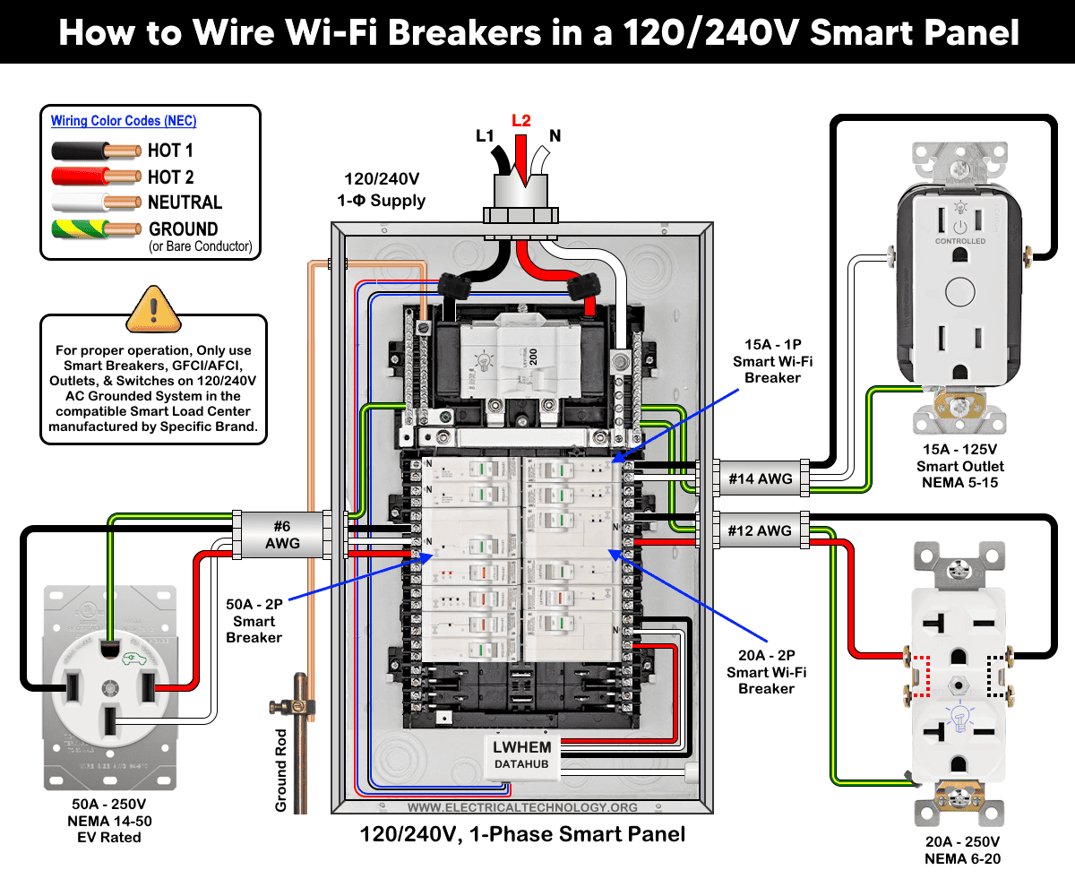
Wiring 1-Pole & 2-Pole Smart Breakers to the Smart & Standard Outlets in a Smart Panel
One advantage is that both standard and smart outlets can be wired within the same 200A smart panel (LP220-BPD).
Following the sequence described above, the load points listed below are connected to smart breakers in the smart panel as shown in the wiring diagram.
- 15A/125V – NEMA 5-15 smart outlet (D215R) through a 1-pole, 15A/120V smart breaker (LB115-ST) using #14-2 wires
- 20A/250V standard outlet (NEMA 6-20) through a 2-pole, 20A/240V smart breaker (LB220-ST) using #12 -2 wires
- 50A – 125/250V EV rated outlet (NEMA 14-50) through a 2-pole, 50A/240V smart breaker (LB250-ST) using #6-3 wires
Click image or open in a new tab to enlarge
For clarity, the following wiring diagram illustrates the connections for 1-pole and 2-pole, 120/240V smart breakers to the respective load points within a smart load center.
Click image or open in a new tab to enlarge
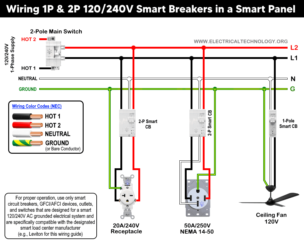
This diagram follows standard National Electrical Code (NEC) color code:
Termination: Wire, AWG, Stripe Length & Torque for Load Center Wiring
The following chart provides reference values for wire size (AWG), conductor strip length, and torque levels required for proper termination during Smart Load Center installation.
Click image or open in a new tab to enlarge
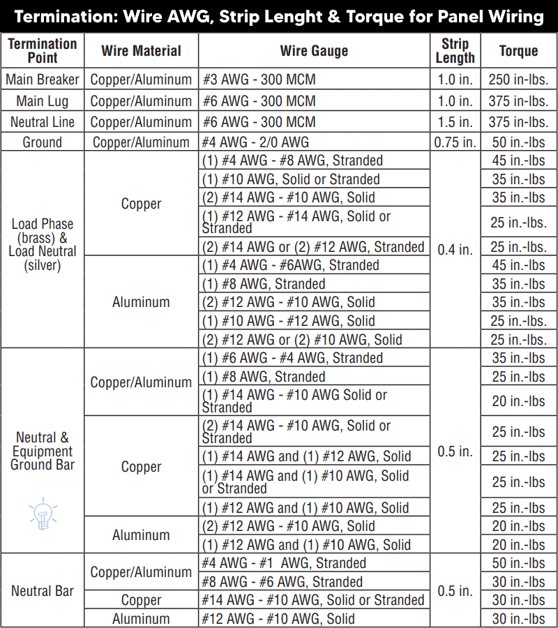
This information applies exclusively to Leviton load centers. For load centers manufactured by other brands, refer to the specific installation manual and user guide provided by the respective manufacturer or consult a licensed electrician.
Precaution & Codes:
- Disconnect the power supply, and verify that it is completely OFF before servicing, repairing, or installing any electrical equipment. Switch OFF the main breaker in the main panel.
- Never touch the terminal screws above the main breaker. These terminals remain energized at all times, regardless of whether the main breaker is in the ON or OFF position.
- Do not touch wet surfaces or metallic parts while working on energized circuits.
- Carefully read and strictly follow all safety instructions related to this guide and to any electrical work you perform.
- Always use the correct wire gauge, properly rated outlets and switches, and appropriately sized circuit breakers. A wire and cable size calculator may be used to determine the correct conductor size.
- Do not use a 15A breaker for 20A load circuits. Doing so may trip unnecessarily under normal usage (e.g., multiple devices drawing 16A).
- Do not use a 20A breaker for 15A load circuits. Doing so will will allow the breaker up to 20A of current to flow, which exceeds the wire’s capacity as well as won’t be able to protect the 15-Amp branch circuit conductors.
- Do not use 20A outlet on 15A circuit breaker. If more than one receptacle on the same circuit, you may allowed to use 15A outlet on 20A circuit breaker.
- It is code to use 15A outlet on 20A breaker (NEC 210.21(B)(2)), but it is not allowed to use 20A outlet on 15A breaker.
- While a 2-Pole 240V breaker can be used on 120V circuits (not a good practice), it is strictly prohibited to use a 1-pole breaker for 240V circuits.
- Do not use three phase breaker for single-phase and vice versa.
- Do not attempt electrical installation or repairs without proper knowledge and training. All work should be performed under the supervision of a qualified and experienced individual.
- Performing electrical work yourself can be hazardous and may be prohibited in some jurisdictions. Consult a licensed electrician and/or your local electrical authority before modifying any wiring system.
- The author assumes no responsibility for any loss, injury, or damage resulting from improper use of this information or incorrect wiring practices. Electricity presents serious hazards, therefore, exercise extreme caution at all times.
Resources:
Smart Devices Wiring Series
- How to Wire a Smart Breaker in a Smart 120/240V Panel
- How to Wire a Smart GFCI Breaker in a 120/240V Smart Panel
Main Panels Wiring Tutorials
- How to Wire 120/240V Main Panel – Breaker Box Installation
- How to Wire 120V/208V, 1-Phase & 3-Phase Main Panel?
- How to Wire 120/208/240V High Leg Delta 1-Phase & 3-Phase Main Panel?
- How to Wire 277/480V, 1-Phase & 3-Phase Main Service Panel?
- How to Wire 347/600V, 1 and 3-Phase Main Service Panel?
- How to Wire a Subpanel? Main Lug Installation for 120V/240V
- How to Wire a Spa Panel Box for a Hot Tub using 2P GFCI & Breaker
- Single Phase Electrical Wiring Installation in Home – NEC & IEC
- Three Phase Electrical Wiring Installation in Home – NEC & IEC
- How To Wire a Single Phase kWh Meter – 120V/240V
- How to Wire a Three-Phase Meter? 120/208/240/277/347/480/600V
Wiring Smart / Standard GFCI & Breakers
- How to Wire a 1-Pole Breaker
- How to Wire a 2-Pole Breaker
- How to Wire a 3-Pole Breaker
- How to Wire a 1-Pole GFCI
- How to Wire a 2-Pole GFCI
- How to Wire a 3-Phase, 3-Pole GFCI
- How to Wire a Tandem Breaker
- How to Wire GFCI Circuit Breakers
- How to Wire an AFCI Breaker
Wiring Smart / General Outlets & GFCI/AFCI Receptacles
- How to Wire an Outlet Receptacle? Socket Outlet Wiring Diagrams
- How to wire a GFCI Outlet?
- How to a Wire 3-Way Combination Switch and Grounded Outlet?
- How to Wire a 15A – 125V Outlet – NEMA 5-15 Receptacle
- How to Wire a 20A – 125V Outlet – NEMA 5-20 Receptacle
- How to Wire a 15A – 250V Outlet – NEMA 6-15 Receptacle
- How to Wire a 20A – 250V Outlet – NEMA 6-20 Receptacle
- How to Wire a 50A – 125/250V Outlet – NEMA 14-50 Receptacle
Switches Wiring
- How to Wire Single Pole, Single Throw (SPST) as 2-Way Switch?
- How to Wire Single Pole, Double Throw (SPDT) as 3-Way Switch?
- How to Wire Double Pole, Single Throw Switch? Wiring DPST
- How to Wire Double Pole, Double Throw Switch? Wiring DPDT
- How to Wire Double Switch? 2-Gang, 1-Way Switch – IEC & NEC
- How to Wire 4-Way Switch (NEC) or Intermediate Switch as 3-Way (IEC)?
- How to Wire Auto & Manual Changeover & Transfer Switch – (1 & 3 Phase)
Sizing Breakers, Wires, and Panels
- How to Size a Load Center, Panelboards and Distribution Board?
- How to Determine the Right Size Capacity of a Subpanel?
- How to Find the Right Wire Size for 100A Service 120V/240V Panel?
- How to Size a Circuit Breaker?
- How to Find the Proper Size of Wire & Cable In Metric & Imperial Systems
- How to Size a Breaker and Wires in AWG with EGC for Load?
- How to Size Service-Entrance Conductors and Feeder Cables?
- How to Size Feeder Conductors with Overcurrent Protection
- How to Size a Branch Circuit Conductors with Protection?
- How to Size Equipment Grounding Conductor (EGC)?
- How to Size Grounding Electrode Conductor (GEC)?
- How to Size Main Bonding Jumper (MBJ)?
- How to Size Motors FLC, HP, Voltage, Breaker Size and Wire Size
- What is the Correct Wire Size for 100A Breaker and Load?
- What is the Right Wire Size for 15A Breaker and Outlet?
- What is the Suitable Wire Size for 20A Breaker and Outlet?
Finding the Number of Breakers/Outlets in a Circuit
- How to Determine the Number of Circuit Breakers in a Panelboard?
- How to Find the Number of Outlets on a Single Circuit Breaker?
- How to Find Voltage & Ampere Rating of Switch, Plug, Outlet & Receptacle
- How to Calculate the Number of Fluorescent Lamps in a Final Sub Circuit?
- How to Calculate the Number of Incandescent Lamps in a Final Sub Circuit?
- How to Determine the Number of Lighting Branch Circuits?
- How to Determine the Number of Branch Circuits? – 3 Ways
- How to Find the Number of Lights on a Single Circuit Breaker?
General Wiring Installation Tutorials:
- How to Toggle Electric Water Heater Between 120V and 240V?
- How to Wire 120V Water Heater Thermostat – Non-Simultaneous?
- How to Wire 240V Water Heater Thermostat – Non-Continuous?
- How to Wire 3-Phase Simultaneous Water Heater Thermostat?
- How to Wire Twin Timer for 120V/240V Circuits – ON/OFF Delay
- How to Wire ST01 Timer with Relay & Contactor for 120V/240V Motors?
- How to Wire Multifunction ON/OFF Delay Timer for 120V/240V Motors?
- Even More Residential Wiring Installation Tutorials


