Wiring a 7.7kW Level 2 EV Wall Charger using Hardwired and Plug-in Connections for Electric Vehicle Charging
Green Motion EV Wall Charger
As electric vehicles (EVs) continue to gain popularity and capture a larger share of the market, more homeowners are looking to install a dedicated EV charging station. Among the various charging solutions available, a Level 2 EV wall charger remains one of the simplest, most practical, and cost-effective options for residential charging.
The Green Motion EV Wall Charger by Eaton is a fast AC 7.7 kW, 32A Level 2 EV charging station equipped with a 25-ft charging cable. It can be installed either as a hardwired unit directly connected to the electrical panel or as a plug-in unit connected to a properly rated receptacle. The charger integrates a 40A thermal-magnetic circuit breaker, GFCI protection, automatic fault-reset functionality, and an SAE J1772 charging connector into a single compact enclosure.
The EV wall charger can be remotely monitored and controlled through a smartphone app. This way, it can be used to schedule charging sessions and manage charging operations from virtually anywhere.
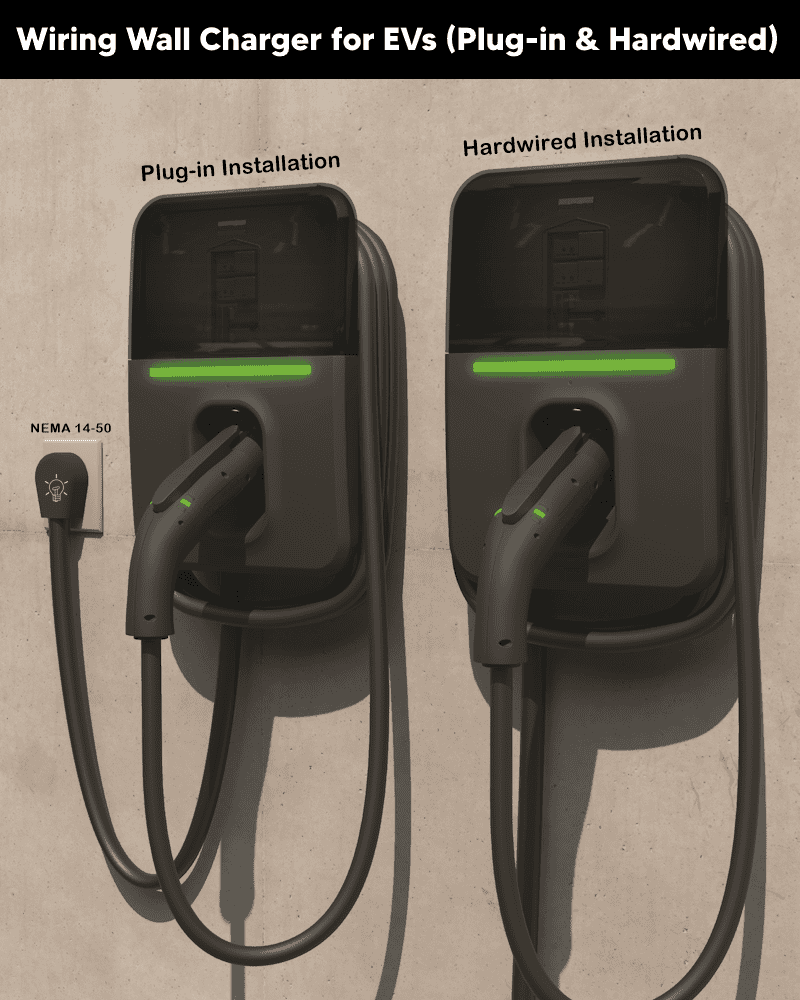
In this EVSE (Electric Vehicle Supply Equipment) wiring series, we will demonstrate the installation and wiring procedures for the Green Motion Level 2 EV Wall Charger by Eaton.
Electrical Ratings & Specifications
- Name: Green Motion EV Wall Charger by Eaton (Hardwired “GMEV32BR-WC” & Plug-in “GMEV32BR-WCPL”)
- Voltage: 208-240V AC – 60 Hz – Single-Phase
- Breaker Rating: 40A
- Charging Current: 32A
- Output Power: 7.7 kW at 240V, 6.6kW at 208V
- GFCI: 20mA Ground Fault Protection
- Wire Size: (Hardwire) = 8 AWG copper (60°C or 75°C) / 6 AWG aluminum (60°C) / 8 AWG aluminum (75°C)
- Connector Type: SAE J1772 with 25ft Cable
- Wireless Connectivity: Smart Control through IEEE 802.11 b/g/n and 2.4 GHz Wi-Fi
- Listed: UL, CSA, NFPA Article 625, SAE J1772 2010 Ed., FCC Compliant, Part 15 and ANSI C12.20
- Wiring Method: Hardwired with 2P 40A Breaker and Plug-in with NEMA 14-50 Plug & Receptacle.
- Enclosure: UL / NEMA Type 3R rated for Indoor / Outdoor Installation
Good to Know: These wiring tutorials applies to Eaton Green Motion EV Wall Chargers (GMEV32BR-WC & GMEV32BR-WCPL) for both hardwired and plug-in installation. The wall charger include built-in EV Smart Breaker Chargers (BREVEM2040 & BABEVEM2040) by Eaton.
Good to Know: 40A Breaker / 32A Charging:
Because EV charging is considered a continuous load (operating for more than 3 hours), the branch circuit must be sized at 125% of the charger output current as per 210.19(A)(1). For a 32A charger:
32A × 125% = 40A
This way, the charger delivers 32A continuously and is designed to be supplied by a 40A branch circuit.
Method 1: Hardwired EV Wall Charger (Direct Connection)
In this wiring method, the EV wall charger is permanently hardwired to the load center (panelboard). This installation method is preferred when the charging cable can easily reach the parked vehicle directly from the panel location.
To install the hardwired wall charger (GMEV32BR-WC), verify that a dedicated 40A, 2-pole circuit breaker is installed in the panel. If one is not already present, install a compatible 40A, 2-pole breaker in two adjacent spaces on the panel busbars.
The charger includes built-in ground-fault protection through its integrated 40A, 2-pole smart breaker charger. Therefore, an additional GFCI breaker is generally not required for a hardwired EVSE installation. In this case, the 40A branch circuit can safely support 32A continuous EV charging.
Click image or open in a new tab to enlarge
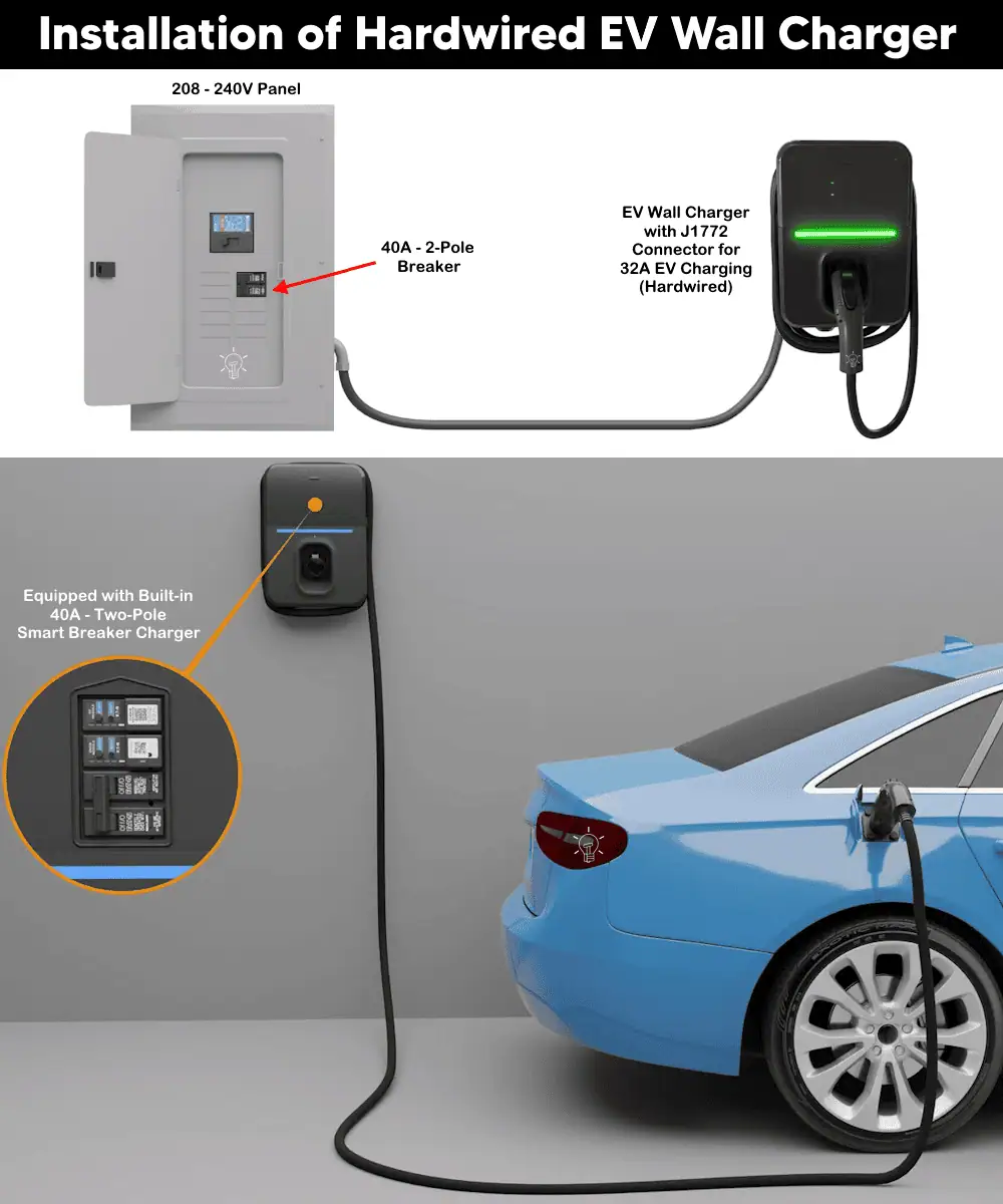
To hardwire the wall charger for EVs, follow the following steps:
Step 1 – De-energize the Circuit
- Turn OFF the main breaker supplying the panel.
- Turn OFF the dedicated 40A double-pole breaker intended for the EV charger.
- Remove the EV wall charger from its packaging, and carefully remove the cover.
- Remove one of the two knockouts on the charger base for your conduit fitting.
- Install an approved conduit fitting (clamps, conduit and UL Type 3R outdoor rating)
Note: For this installation method, use a dedicated 2-pole, 40A overcurrent protective device for branch circuit protection.
Step 2 – Mount the Charger Base
- Mark the wall location using the provided mounting template.
- Mount the EV wall charger base to the wall using the supplied #14 x 2″ screws and anchors (4 each), fastened through the surface mounting holes.
Good to Know: According to NEC Article 625, the installation height recommendation for:
- Indoor connector storage height: 18 in. minimum above floor.
- Outdoor connector storage height: 24 in. minimum above grade.
Step 3 – Install Conduit
- Route your conduit to the knockout you opened in Step 1 and .
- Run branch-circuit conductors through the conduit.
- Connect the conduit to the charger enclosure.
Step 4 – Wire the Charger (Main Wiring Step)
This unit supports two electrical service types:
- 240 V AC Split-phase, 3-wire
- 208 V AC Wye, 3-Wire
Neutral (with ground) is required for both systems.
Wire Size:
- Use 8 AWG copper, or 6 AWG aluminum at 60°C wire
- or 8 AWG copper or 8 AWG aluminum at 75°C wire:
Connect four conductors to the terminal block:
| Terminal | Wire Color | Function |
| L2 | BLACK | Line 2 (Hot 2) |
| L1 | RED | Line 1 (Hot 1) |
| N | WHITE | Neutral |
| G | GREEN | Ground |
- Install the two line (hot) conductors, the neutral, and the ground wire into their respective terminals.
- Torque the wire pressure screws to the exact value printed on the wiring label inside the cover.
- Plug in the two wiring harness connectors running from the base into the circuit board on the cover. These carry low-voltage control/communication signals between the base and the cover electronics – they’re keyed, so they only seat one way.
Click image or open in a new tab to enlarge
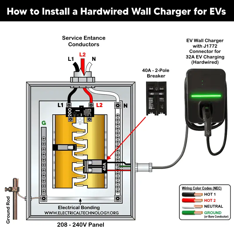
Good to Know: Grounding: This is a permanently connected product. It must be connected to a grounded, metal, permanent wiring system, or an equipment grounding conductor (EGC) must run with the circuit conductors back to the panel’s grounding terminal.
Step 5 – Reinstall the Front Cover
- Align the two bottom tabs on the cover with the slots in the base.
- Fasten using the tamper-resistant screws provided, torqued to 15 in-lb using the supplied T25 Torx bit.
- Secure the remaining two mounting holes under the lid with tamper-resistant screws, also torqued to 15 in-lb.
Step 6 – Restore Power to Energize the charger
- Before energizing, re-check every electrical connection.
- Reconnect power to the upstream circuit by switching the 40A breaker to ON.
- Energize the loadcenter/panelboard by switching ON the main breaker in the panel. The charger’s electronics should power immediately; the BlinkUp status LED will begin blinking, and the EV connector LEDs will start blinking as well.
- Move the EV smart breaker charger handle from OFF to ON to fully energize the unit.
- Proceed to Wi-Fi Commissioning below.
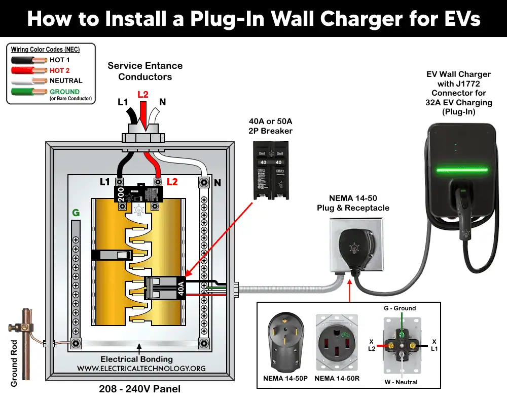
Method 2: Plug-In EV Wall Charger Installation with NEMA 14-50
In this method, the EV wall charger is plugs into an EV rated NEMA 14-50 receptacle. This installation method is preferred when the vehicle parking location is farther away from the panel.
To install the plug-in wall charger (GMEV32BR-WCPL), make sure a NEMA 14-50 receptacle wired through a dedicated 2-pole 40A/50A circuit breaker is already installed near the parking or where you want to install the charger. If one is not already present, install a compatible EV rated NEMA 14-50 receptacle supplied by a 2-pole, 40/50A breaker.
Since the charger has a built-in Ground-Fault Circuit Interrupter (GFCI) protection, so no need to install another GFCI breaker in the panel. Instead, the 40A / 50A breaker is enough to support the 40A wall charger for 32A EV charging.
Click image or open in a new tab to enlarge
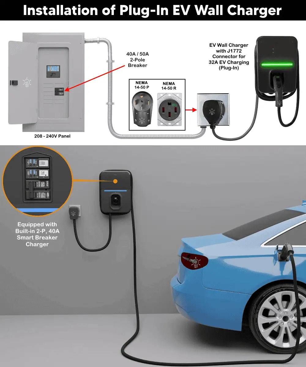
For plug-in wall charger installation, follow the following steps:
Step 1 – Disconnect the Power and Install the NEMA 14-50 Receptacle
- Confirm the dedicated 40A or 50A, 2-pole upstream breaker feeding the receptacle is OFF.
- Confirm receptacle mounting height before proceeding:
- Indoor: NEMA 14-50R receptacle must be at least 18 inches above the floor.
- Outdoor: NEMA 14-50R receptacle must be at least 24 inches above grade.
Good to Know: Eaton recommends a BR240H (40A) or BR250H (50A) circuit breaker, or an equivalent 240V-rated two-pole device.
To wire the NEMA 14-50 receptacle, connect the four wires as follow:
- X terminal to Hot 1 i.e. L1 (Black wire)
- Y terminal to Hot 2 i.e. L2 (Red wire)
- W terminal to Neutral ( White wire )
- G terminal to Ground (Green/Bare wire)
Click image or open in a new tab to enlarge
Good to Know:
- The wall charger include the bult-in 2ft cable with NEMA 14-50P (plug), so that, it can be plugged into the NEMA 14-50R (receptacle).
- The receptacle must be fed by a dedicated branch circuit – no other outlets or loads sharing the line (NEC 625.40 / dedicated circuit requirement).
- Wire gauge: Minimum 6 AWG copper in a 4-wire configuration (hot/hot/neutral/ground) for a 50A circuit. Sizing depends per your breaker rating and local code.
- GFCI protection: NEC 210.8(A) requires GFCI protection for 125-250V receptacles in garages and similar listed locations, and NEC 625.54 separately requires GFCI protection for receptacles used specifically for EV charging. In practice this generally means a listed 2-pole GFCI breaker feeding the receptacle. Since this charger has its own internal 20 mA ground-fault protection (UL 2231-2 compliant) and pairing it with an external GFCI breaker can occasionally cause nuisance tripping due to differing trip sensitivities.
- Outdoor installs: The receptacle enclosure must be weatherproof with the plug both inserted and removed (NEC 625.56) – use an “in-use” rated, extra-duty weatherproof cover.
- Torque all receptacle terminal screws to the receptacle manufacturer’s specified torque value – “hand tight” is not sufficient per NEC 110.14(D).
Warning: Do not plug the charger in yet as the installation is not completed yet – wait until Step 5 below.
Step 3 – Mount the Charger Base
- Mark the wall location using the mounting template and make holes.
- Remove the front cover from the wall charger.
- Mount the EV wall charger base using the supplied #14 x 2″ screws and anchors (4 each).
Step 4 – Wire the Internal Connectors
Unlike the hardwire version, the plug-in unit arrives with its pre-installed NEMA 14-50P plug and cordset. Hence, there is no need to installed the NEMA 14-50 plug in this setup.
Plug in the two wiring harness connectors from the base into the circuit board on the cover (same keyed connectors as the hardwire version – they only fit one way).
The harness connectors inside the wall charger are connected to the smart breaker charger as follow:
3-Wire Connector
- Black = Either Line 1 or Line 2
- White = Neutral
- Green = Ground
2-Wire Connector
- Blue: +12 VDC
- Orange: J1772 Pilot
Step 5 – Install the Cover and Plug In
- Align the two bottom tabs with the slots in the base; fasten with the tamper-resistant screws, torqued to 15 in-lb.
- Fasten the remaining two mounting holes under the lid the same way, torqued to 15 in-lb.
- Now plug the NEMA 14-50P plug into the NEMA 14-50R receptacle.
Step 6 – Re-energize and Test
- Re-check all connections before energizing.
- Reconnect power to the upstream breaker (ON position).
- Energize the panel. The charger electronics should power immediately; BlinkUp status LED and EV connector LEDs will begin blinking.
- Move the EV smart breaker charger handle from OFF to ON.
- Proceed to Wi-Fi Commissioning below for smart control and scheduling.
Configuration and Wi-Fi Network Setting
The wall charger can be controlled remotely through a Wi-Fi network. The wall charger operation such as start, stop, monitor, and manage charging sessions can be controlled from anywhere. Moreover, it can be configured for schedule charging sessions based on Time-of-Use (TOU) utility rates to help reduce overall charging costs.
In addition, the wall charger cab be added to your preferred charge-management solution. To do so, download the EM Install app.
Once either installation method is completed and the circuit is energized:
- Ensure a Wi-Fi signal is available at the install location.
- Download the Brightlayer Home app (iOS or Google Play).
- In the app: name your charger, enter your Wi-Fi credentials, and follow the BlinkUp pairing steps (hold your phone screen against the charger’s status LED as prompted).
- For integration with a third-party charge management system, see Eaton’s developer portal (eaton.com/developer) for API documentation, then use the EM Install app to commission the unit.
For Wi-Fi setup, app pairing, and advanced smart-control features, follow the step-by-step instructions in the guides below:
- Connect Eaton’s EV Wall Charger to the EV Charger Manager app.
- Connect Eaton’s EV Wall Charger to Charging Network Manager using the EM Install app.
- Connect Eaton’s EV Wall Charger to the Brightlayer Home app.
Note: Only the GMEV32BR-WC model (hardwired) can be controlled through the app. In other words, the mobile app connectivity feature in not available in the The GMEV32BR-WCPL (plug-in) model.
Troubleshooting
| LED Status | Indication and Causes |
| LED bar completely off | Check the harness cable between base and front cover – improperly seated connectors cause this. |
| Red LED blinking half-second on/off | Loss of line-side power – turn breaker off and recheck line wiring. |
| Red LED blinking one-second on/off | Active fault condition – clear via 3 presses of the smart breaker display button (if applicable). |
| Breaker tripped, won’t reset | Push handle fully to OFF, then back to ON – it behaves like a standard Eaton BR thermal-magnetic breaker. |
| “NO INTERNET” in app | Verify both the phone and the charger have active internet/Wi-Fi connectivity. |
Instruction and Precautions
- Remove all power sources to the panel before starting installation or maintenance.
- Make sure the installation complies NEC Article 625 for EV charging, plus applicable Articles i.e. 110, 210, 220, 240, and 310. In addition, follow your local Authority Having Jurisdiction (AHJ) if applicable.
- Install in accordance with the National Electrical Code (NEC), the Canadian Electrical Code (CEC), and all applicable local amendments. Check with your local electrical inspector before starting.
- Per NEC Article 625, the EV connector holster must be mounted between 18 in. (450 mm) and 4 ft (1.2 m) above floor level indoors, and at least 24 in. (600 mm) above grade outdoors.
- Risk of Explosion: this equipment has arcing/sparking parts and must be located at least 18 in. (460 mm) above the floor, away from flammable vapors.
- This equipment must be installed, adjusted, and serviced only by qualified electrical personnel familiar with this type of equipment and its hazards.
- Failure to follow these instructions could result in death, personal injury, or property damage.
Disclaimer:
The author will not be liable for any losses, injuries, or damages from the display or use of this information or if you try any circuit in wrong format. So please! Be careful because it’s all about electricity and electricity is too dangerous. If you are unsure, contact a licensed electrician to do it according to the local area codes.
Resources:
EV Charger Wiring Series
- How to Wire AC Level 2 EV Smart Breaker Charger – 40A/32A
- How to Wire ChargePoint Home Flex Charger for Every EV
- How to Wire Smart Electric Vehicle Charging Station – 32A/80A
- How to Wire 48A Level 2 Dual Port EV Charging Station
- How to Wire and Use Tesla Gen 3 Mobile Connector Charger
- How to Wire a Tesla Wall Connector & Universal EV Charger
Smart Devices Wiring Series
- How to Wire a Smart Switch in a 120/240V Load Center
- How to Wire 120/240V Smart Load Center with Smart Breakers
- How to Wire a Smart Breaker in a Smart 120/240V Panel
- How to Wire a Smart GFCI Breaker in a 120/240V Smart Panel
- How to Wire Smart AFCI/GFCI Breaker in a Smart Load Center
- How to Wire a 15A Wi-Fi Smart Outlet in a Smart Panel
- How to Wire 15A and 20A Wi-Fi Smart GFCI Outlets
- How to Wire Z-Wave Smart Switch, Dimmer & Fan Speed Controller
- How to Wire a Digital and Wi-Fi Smart LED Dimmer Switch
- How to Wire a Smart Switch Companion with a Smart Switch
- Wiring a Smart Dimmer Switch Companion with a Digital Dimmer
- How to Install a Wire-Free Smart Dimmer Anywhere Companion
- How to Wire Smart Scene Controller Switch
- How to Install a Wireless Smart Scene Switch
- How to Install a Wake and Sleep Wireless Smart Switch
- How to Wire a Smart Motion Sensing Dimmer Switch
- How to Wire a Combo Humidity Sensor & Fan Control with Light Switch
- How to Wire Humidity Sensor and Fan Control Switch
- How to Wire a Countdown Timer Switch – 15 Mins to 12Hrs
Wiring Standard GFCI & Breakers
- How to Wire a 1-Pole Breaker
- How to Wire a 2-Pole Breaker
- How to Wire a 3-Pole Breaker
- How to Wire a 1-Pole GFCI
- How to Wire a 2-Pole GFCI
- How to Wire a 3-Phase, 3-Pole GFCI
- How to Wire a Tandem Breaker
- How to Wire GFCI Circuit Breakers
- How to Wire an AFCI Breaker
Main Panels Wiring Tutorials
- How to Wire 120V/240V Main Panel? Breaker Box Installation
- How to Wire 120/240V Smart Load Center with Smart Breakers
- How to Wire 208V/120V, 1-Phase & 3-Phase Main Panel?
- How to Wire 240V, 208V & 120V, 1 & 3-Phase, High Leg Delta Main Panel?
- How to Wire 277V/480V, 1-Phase & 3-Phase Main Service Panel?
- How to Wire a Subpanel? Main Lug Installation for 120V/240V
- Single Phase Electrical Wiring Installation in Home according to NEC & IEC
- Three Phase Electrical Wiring Installation in Home – NEC & IEC
- How To Wire a Single Phase kWh Meter – 120V/240V
- How to Wire a Three-Phase Meter? 120/208/240/277/347/480/600V
- How to Wire Spa Panel for Hot Tub using 2-P GFCI & Breaker
Wiring General Outlets & GFCI/AFCI Receptacles
- How to Wire an Outlet Receptacle? Socket Outlet Wiring Diagrams
- How to wire a GFCI Outlet?
- How to Wire an AFCI Outlet?
- How to a Wire 3-Way Combination Switch and Grounded Outlet?
- How to Wire a 15A – 125V Outlet – NEMA 5-15 Receptacle
- How to Wire a 20A – 125V Outlet – NEMA 5-20 Receptacle
- How to Wire a 15A – 250V Outlet – NEMA 6-15 Receptacle
- How to Wire a 20A – 250V Outlet – NEMA 6-20 Receptacle
- How to Wire a 30A – 250V, NEMA 6-30 Receptacle
- How to Wire a 50A – 125/250V Outlet – NEMA 14-50 Receptacle for EVs
Sizing Breakers, Wires & Panels
- How to Size a Load Center, Panelboards and Distribution Board?
- How to Determine the Right Size Capacity of a Subpanel?
- How to Find the Right Wire Size for 100A Service 120V/240V Panel?
- How to Size a Circuit Breaker?
- How to Find the Proper Size of Wire & Cable In Metric & Imperial Systems
- How to Size a Breaker and Wires in AWG with EGC for Load?
- How to Size Service-Entrance Conductors and Feeder Cables?
- How to Size Feeder Conductors with Overcurrent Protection
- How to Size a Branch Circuit Conductors with Protection?
- How to Size Equipment Grounding Conductor (EGC)?
- How to Size Grounding Electrode Conductor (GEC)?
- How to Size Main Bonding Jumper (MBJ)?
- How to Size Motors FLC, HP, Voltage, Breaker Size and Wire Size
- What is the Correct Wire Size for 100A Breaker and Load?
- What is the Right Wire Size for 15A Breaker and Outlet?
- What is the Suitable Wire Size for 20A Breaker and Outlet?
-
 BYD Orders 10 More Ships to Carry 130,000+ EVs Worldwide
-
 BYD Launches Electric Truck to Rival Tesla Semi in Europe
-
 BYD’s New Electric Truck for EU Beats Tesla Semi in Almost Every Metric
-
 Windrose Electric Trucks Enter Australia’s Long-Haul Freight
-
 Germany’s Electric Drone Hits 699 km/h, Eyes World Record
-
 How to Wire and Use Tesla Gen 3 Mobile Connector Charger