Three Phase AC Circuits MCQs With Explanatory Answers
Three Phase AC Circuits (MCQs With Explanatory Answers)
Three Phase AC Circuits MCQs with explanation. For explanatory answer, click on the toggle button labeled as “Check explanatory answer”.
Q1. Electric power in a Three Phase Circuit = _________.
- P = 3 VPh IPh CosФ
- P = √3 VL IL CosФ
- Both 1 & 2.
- None of The Above
Explanatory Answer: [For a Delta Connection] [VPh = VL and IPh = IL/√3.] then putting the values in eq …..(1) Also [VPh = VL/√3 and IPh = IL]Show Explanatory Answer
Total Power in a Three Phase Circuit,
P = 3 x Power per Phase,
P = 3 x VPh IPh CosФ
P = 3 VPh IPh CosФ…………(1)
P = 3 x VL x ( IL/√3) x CosФ
P = √3 x√3 x VL x ( IL/√3) x CosФ …{ 3 = √3x√3 }
P = √3 x VLx IL x CosФ ….Ans.
[For Star Connection]
Putting the values again in eq…….(1)
P = 3 x (VL/√3 ) x IL x CosФ
P = √3 x√3 x (VL/√3 ) x IL x CosФ …{ 3 = √3x√3 }
P = √3 x VL x IL x CosФ ….Ans.
Q2. A polyphase system is generated by ________ ?
- Having two or more generator windings separated by equal electrical angle.
- Having generator windings at equal distances
- None of the above
- A and C
Explanatory Answer: A generator having two or more electrical windings which are separated by equal electrical angle generates a polyphase electrical system. The electrical angle or displacement depends upon the number of windings or phases. For example, in a three-phase electrical system, the generated voltages are separated from each other by 120° degrees.
Show Explanatory Answer
Q3. In a three phase AC circuit, the sum of all three generated voltages is ________ ?
- Infinite (∞)
- Zero (0)
- One (1)
- None of the above
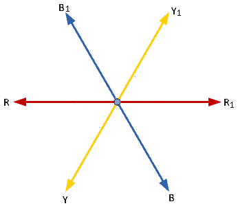
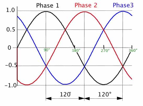
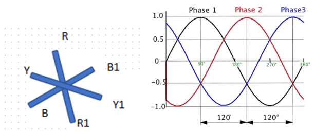
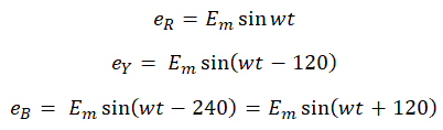
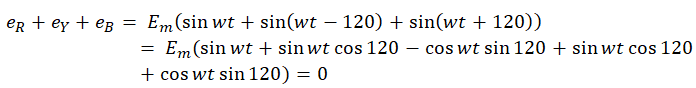
Explanatory Answer: Three phase voltages are generated by having an alternator with three armature windings such that each winding is displaced from the other by 120 degrees. When these windings are placed in a rotating magnetic field or rotated in a stationary magnetic field, electromotive force is generated in each coil, of same magnitude and direction. Consider the below diagram Figure : 3 Phase AC Waveforms As seen EMF generated in coil R-R1 is eR, which is the reference in this case. EMF generated in coil Y-Y1 is eY which is 120° degrees ahead of eR and EMF generated in coil B-B1 is eB which is 240° degrees ahead of eR. Therefore the voltage equations are as given below; Hence, sum of all three voltages is zero.
Show Explanatory Answer
Q4. For a star connected three phase AC circuit ________ ?
- Phase voltage is equal to line voltage and phase current is three times the line current
- Phase voltage is square root three times line voltage and phase current is equal to line current
- Phase voltage is equal to line voltage and line current is equal to phase current
- None of the above
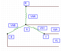
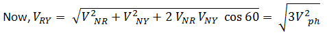
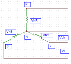
Explanatory Answer: A star connected AC circuit is achieved by connecting each end of the winding to a common point known as neutral point and leaving the other end of each winding free. While voltage across each coil is the phase voltage, potential difference between each free end is the line voltage. Consider the circuit below; Now as said above, phase voltages are equal Hence, VNR = VNY = VNB = Vph Therefore, line voltage, VRY = √3 VPH Since the line conductor is in series with the phase winding, same current will flow through the line conductor as through the phase windings, hence phase current is equal to phase current.
Show Explanatory Answer
Q5. In a three phase, delta connection ________ ?
- line current is equal to phase current
- Line voltage is equal to phase voltage
- None of the above
- Line voltage and line current is zero
Explanatory Answer: A delta connected AC circuit is achieved by connecting the start end of a winding to the finish end of another winding such that all three windings form a mesh. Since each end of the windings forms the line connection, voltage across each winding is equal to the potential difference between the corresponding lines taken from that winding. Hence the phase voltage is equal to the line voltage.
Show Explanatory Answer
Q6. For a star connection network, consuming power of 1.8kW and power factor 0.5, the inductance and resistance of each coil at a supply voltage of 230 Volts, 60 Hz is ________ ?
- 0.1H, 8 Ohms
- 0.5H, 10 Ohms
- 0.3H, 7.4 Ohms
- 1H, 7 Ohms
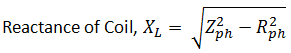
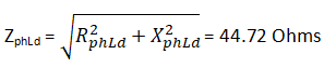
Explanatory Answer: Given values are: Line voltage, VL = 230 V Line frequency, f = 60 Hz Power Factor, cosφ = 0.5 Power consumed = P = 1800 Watts = √3 VL x IL x cosφ Hence, line current, IL = 9 Amperes Since it is a star connection, phase current = line current = 9 Amperes Phase Voltage, Vph = VL/√3 = 132.8 Volts Phase Impedance, Zph = Vph/Iph = 14.7 Ohms Now, Power Factor = Resistance/Impedance Hence, Resistance of Coil = Impedance X Power Factor = 7.4 Ohms Substituting values, we get Reactance of coil = 12.7 Ohms Thus, inductance of coil , L = 0.03H
Show Explanatory Answer
Q7. For a three-phase delta connected load, fed from a star connected network, the power transferred to the load is ________ ?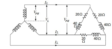
- 3 kW
- 4.7 kW
- 5 kW
- 7 kW
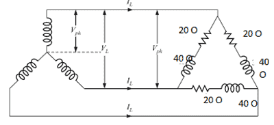
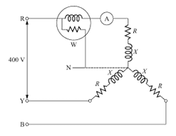
Explanatory Answer: Given values: Star Connected phase voltage, VPH = 230 Volts Phase load resistance, RPHLd = 20 Ohms Phase load reactance, XPHLd= 40 Ohms Hence, phase load impedance, Star connected line voltage, VL = VPHs = 398.37 Volts For the delta connected load, Phase Voltage, VPHLd = VL = 398.37 Volts Therefore, current through each phase of load, IPHLd = VPHLd / ZPHLd = 8.9 Amperes Line current for delta connected load, IL = √3 IPHLd = 15.41 Amperes Power Factor, pfs = RphLd/ ZPHLd = 0.44 Thus, the power supplied to load then, PL = VL IL pfs = 4.7 KW
Show Explanatory Answer
![]()
Q8. In a three phase AC circuit, power is measured using a Wattmeter.
- True
- False
Explanatory Answer: Power is measured using a Wattmeter which consists of two coils – Current coil, connected in series with the load, carrying the load current and Voltage coil, connected in parallel to the load.
Show Explanatory Answer
Q9. For a polyphase system, the number of Wattmeter required to measure power is equal to ________ ?
- Number of wires
- One less than number of wires
- Number of phases
- None of the above
Explanatory Answer: The number of Wattmeter required to measure power in a polyphase system is determined using Blondell’s theorem. According to this, the number of Wattmeter required is equal to one less than the number of wires in the circuit. For example, in a three phase, four wire system (Star network), the number of Wattmeter required is three.
Show Explanatory Answer
Q10. For the below star connected network of equal resistances, if the Wattmeter reading is 5kW and ammeter reading is 25 Amperes, the power factor, resistance and inductance are ________ respectively.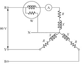
- 1.5 Ohms, 0.1H
- 0.866, 8 Ohms, 0.02H
- 5.10 Ohms, 0.01H
- 4. Ohms, 0.02H
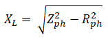
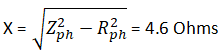
Explanatory Answer: Given Line Voltage, VL = 400 Volts Frequency, f = 60 Hz Line Current, IL = 25 Amperes Power per phase, Pph = 5kW Phase Voltage, Vph = VL/3^1/2 = 230.9 Volts Phase current, Iph = 25 Amperes Hence, power factor, cosφ = Pph/VphIph = 0.866 Impedance, Zph = Vph/Iph = 9.236 Ohms Resistance, R = Zphcosφ = 8 Ohms Putting the values in the below equation, Reactance, X = Show Explanatory Answer
 Therefore, Inductance, L = 0.02H
Q11. For a three phase, three wire system, the two Wattmeter read 4000 Watts and 2000 Watts respectively. The power factor when both meters give direct reading is ________ ?
- 1
- 0.5
- 0.866
- 0.6
Explanatory Answer: Reading of Wattmeter 1, W1 = 4000 Watts Reading of Wattmeter 2, W2 = 2000 Watts Phase angle; Power Factor, = 0.866
Show Explanatory Answer
![]()
Q12. For a balanced three phase, three wire system with input power of 10kW, at 0.9 power factor, the readings on both wattmeter are ________ respectively
- 7kW, 3kW
- 6350W, 3650W
- 5000W, 5000W
- 7600W, 1200W
Explanatory Answer: Let reading of one Wattmeter = W1 Reading of second Wattmeter = W2 Input Power, P = W1+W2 = VL IL cosφ = 10 kW … (1) Power Factor, cos φ = 0.9 Phase angle, φ = 25.8 degrees … (i.e. Cos -1 = 09 = 25.8°) Therefore, W1 = VL IL cos (30 – φ) = 0.99VL IL = 6350W W2 = VL IL cos (30 + φ) = 0.56 VL IL = 3650W
Show Explanatory Answer
Q13. A polyphase system is generated by ________.
- Having two or more generator windings separated by equal electrical angle.
- Having generator windings at equal distances
- None of the above
- A and C
Answer: ( 1 ) Explanatory Answer: A generator having two or more electrical windings which are separated by equal electrical angle generates a polyphase electrical system. The electrical angle or displacement depends upon the number of windings or phases. For example, in a three-phase electrical system, the generated voltages are separated from each other by 120 degrees.
Show Explanatory Answer
Q14. In a three phase AC circuit, the sum of all three generated voltages is ________ ?
- Zero
- One
- None of the above
Answer: ( 2 ) Explanatory Answer: Three phase voltages are generated by having an alternator with three armature windings such that each winding is displaced from the other by 120 degrees. When these windings are placed in a rotating magnetic field or rotated in a stationary magnetic field, electromotive force is generated in each coil, of same magnitude and direction. Consider the below diagram. Figure 1: 3 Phase AC Waveforms As seen EMF generated in coil R-R1 is eR, which is the reference in this case. EMF generated in coil Y-Y1 is eY which is 120 degrees ahead of eR and EMF generated in coil B-B1 is eB which is 240 degrees ahead of eR. Therefore the voltage equations are as given below Adding all three equations, we get Hence, sum of all three voltages is zero.
Show Explanatory Answer
Q15. For a star connected three phase AC circuit ________ ?
- Phase voltage is equal to line voltage and phase current is three times the line current
- Phase voltage is square root three times line voltage and phase current is equal to line current
- Phase voltage is equal to line voltage and line current is equal to phase current
- None of the above
Answer: ( 2 ) Explanatory Answer: A star connected AC circuit is achieved by connecting each end of the winding to a common point known as neutral point and leaving the other end of each winding free. While voltage across each coil is the phase voltage, potential difference between each free endis the line voltage. Consider the below circuit Now as said above, phase voltages are equal Hence, VNR = VNY = VNB = Vph Now, Therefore, line voltage, VRy = Vph √3 Since the line conductor is in series with the phase winding, same current will flow through the line conductor as through the phase windings, hence phase current is equal to phase current.
Show Explanatory Answer
![]()
![]()
Q16. In a three phase, delta connection ________ ?
- line current is equal to phase current
- Line voltage is equal to phase voltage
- None of the above
- Line voltage and line current is zero
Answer: ( 2 ) Explanatory Answer: A delta connected AC circuit is achieved by connecting the start end of a winding to the finish end of another winding such that all three windings form a mesh. Since each end of the windings forms the line connection, voltage across each winding is equal to the potential difference between the corresponding lines taken from that winding. Hence the phase voltage is equal to the line voltage.
Show Explanatory Answer
Q17. For a star connection network, consuming power of 1.8kW and power factor 0.5, the inductance and resistance of each coil at a supply voltage of 230 Volts, 60 Hz is ________.
- 0.01H, 8 Ohms
- 0.05H, 10 Ohms
- 0.03H, 7.4 Ohms
- 1H, 7 Ohms
Answer: ( 3 ) Explanatory Answer: Given values are: Line voltage, VL = 230 V Line frequency, f = 60 Hz Power Factor, cosφ = 0.5 Power consumed = P = 1800 Watts = √3VLILcosφ Hence, line current, IL = 9 Amperes Since it is a star connection, phase current = line current = 9 Amperes Phase Voltage, Vph = VL/3^1/2 = 132.8 Volts Phase Impedance, Zph = Vph/Iph = 14.7 Ohms Now, Power Factor = Resistance/Impedance Hence, Resistance of Coil = Impedance X Power Factor = 7.4 Ohms Reactance of Coil, Substituting values, we get Reactance e of coil = 12.7 Ohms Thus, inductance of coil , L = 0.03H
Show Explanatory Answer
Q18. For a three-phase delta connected load, fed from a star connected network, the power transferred to the load is ________.
- 3 KW
- 7 KW
- 5 KW
- 7KW
Answer: ( 2 ) Explanatory Answer: Given values: Star Connected phase voltage, Vphs = 230 Volts Phase load resistance, RphLd = 20 Ohms Phase load reactance, XphLd = 40 Ohms Hence, phase load impedance, = Star connected line voltage, VL =√3Vphs = 398.37 Volts For the delta connected load, Phase Voltage, VphLd = VL = 398.37 Volts Therefore, current through each phase of load, IphLd = VphLd/ZphLd = 8.9 Amperes Line current for delta connected load, IL = √3IphLd = 15.41 Amperes Power Factor, pfs = RphLd/ZphLd = 0.44 Thus, power supplied to load, PL =√3 VLILpfs = 4.7 KW
Show Explanatory Answer
Q19. In a three phase AC circuit, power is measured using a Wattmeter.
- True
- False
Answer: ( 1 ) Explanatory Answer: Power is measured using a Wattmeter which consists of two coils – Current coil, connected in series with the load, carrying the load current and Voltage coil, connected in parallel to the load.
Show Explanatory Answer
Q20. For a polyphase system, the number of Wattmeter required to measure power is equal to ——
- Number of wires
- One less than number of wires
- Number of phases
- None of the above
Explanatory Answer: The number of Wattmeter required to measure power in a polyphase system is determined using Blondell’s theorem. According to this, the number of Wattmeter required is equal to one less than the number of wires in the circuit. For example, in a three phase, four wire system (Star network), the number of Wattmeter required is three.
Show Explanatory Answer
Q21. For the below star connected network of equal resistances, if the Wattmeter reading is 5kW and ammeter reading is 25 Amperes, the power factor, resistance and inductances ________ respectively
- 1, 5 Ohms, 0.1H
- 0.866, 8 Ohms, 0.02H
- 0.5, 10 Ohms, 0.01H
- 0.4, 8 Ohms, 0.02H
Explanatory Answer: Given Line Voltage, VL = 400 Volts Frequency, f = 60 Hz Line Current, IL = 25 Amperes Power per phase, Pph = 5kW Phase Voltage, Vph = VL/3^1/2 = 230.9 Volts Phase current, Iph = 25 Amperes Hence, power factor, cosφ = Pph/VphIph = 0.866 Impedance, Zph = Vph/Iph = 9.236 Ohms Resistance, R = Zphcosφ = 8 Ohms Reactance, Therefore, Inductance, L = 0.02H
Show Explanatory Answer
Q22. For a three phase, three wire system, the two Wattmeter read 4000 Watts and 2000 Watts respectively. The power factor when both meters give direct reading is ________.
- 1
- 0.5
- 0.866
- 0.6
Answer: ( 3 ) Explanatory Answer: Reading of Wattmeter 1, W1 = 4000 Watts Reading of Wattmeter 2, W2 = 2000 Watts Phase angle, Power Factor, = 0.866
Show Explanatory Answer
![]() = 30 degrees
= 30 degrees
Q23. For a balanced three phase, three wire system with input power of 10kW, at 0.9 power factor, the readings on both wattmeter are ________ respectively
- 7kW, 3kW
- 6350W, 3650W
- 5000W, 5000W
- 7600W, 1200W
Answer: ( 2 ) Explanatory Answer: Let reading of one Wattmeter = W1 Reading of second Wattmeter = W2 Input Power, P = W1+W2 = √3VLILcosφ = 10000 … (1) Power Factor, cosφ = 0.9 Phase angle, φ = 25.8 degrees Therefore, W1 = VLILcos(30-φ) = 0.99VLIL = 6350W W2 = VLILcos(30+φ) = 0.56VLIL = 3650W
Show Explanatory Answer
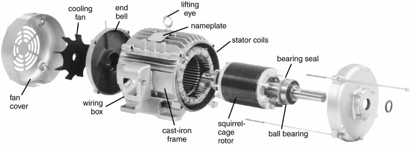
Q24. In a three-phase Induction motor the electrical energy supplied to the stator windings is converted to mechanical energy in form of rotating rotor windings
- True
- False
Answer: ( 1 ) Explanatory Answer:
Figure 1: 3 Phase Induction Motor A three-phase induction motor consists of two parts – Stator (the stationary part) and Rotor (the rotatory part) with the latter being separated from the former by a small air gap. Three phase voltage supplied to the stator windings produces a rotating magnetic field. As the magnetic flux cuts the rotor windings through the air gaps, EMF is induced in the winding which in turn induces current. As the induced current interacts with the stator field, forces are produced which causes the rotor windings to rotate.
Show Explanatory Answer
Q25. The name of the Induction motor comes from the fact that ________.
- Operation of the motor depends upon the induced voltage in the stator
- Operation of the motor depends upon the value of coil windings
- Operation of the motor depends upon the induced voltage in the rotor conductors
- None of these
Answer: ( 3 ) Explanatory Answer: The rotating magnetic field produced by the stator winding on being subjected to a three-phase supply, causes an induction of voltage in the stationary rotor windings. As the rotor circuit is complete, current starts flowing due to the induced voltage. This induced current in turn produces its own magnetic field. As the current carrying conductors are placed in the magnetic field, a force is produced, which acts tangentially and develops a torque which causes the rotor conductors to rotate. Thus, operation of the motor depends upon the induced voltage in the rotor conductors and the motor is called Induction Motor.
Show Explanatory Answer
Q26. An induction motor is ________.
- Self-starting
- Requires external supply
- A or C
- None of these
Answer: ( 1 ) Explanatory Answer: As the rotation of the rotor conductors are initiated normally due to the force produced because of interaction between induced current and rotor magnetic field, no external supply is required and the Induction motor is self-starting.
Show Explanatory Answer
Q27. Slip of an induction motor lies between ________.
- 0 to 10 %
- 0 to 400 RPM
- 0 to 5 %
- 0 to 4000 RPM
Answer: ( 3 ) Explanatory Answer: Slip is the difference between the speed of rotating field and actual speed of rotor. The speed of the rotor must be less than the speed of the rotating field, else there would be no relative motion and the rotary motion would cease to exist. The speed of the rotor should be such that the magnitude of the rotor current is enough to exert the necessary torque. The slip speed denotes the speed of rotor relative to that of the field. Though it is measured in revolutions per minute, more commonly it is denoted in percentage and ranges from 0 to 5%.
Show Explanatory Answer
Q28. In a three-phase induction motor, frequency of the rotor current is ________.
- Equal to the supply frequency
- Proportional to the slip and supply frequency
- Equal to the one less than supply frequency
- Equal to the synchronous speed
Answer: ( 2 ) Explanatory Answer: An induction motor is likea transformer in the fact that both comprise of transfer of energy from a primary winding to secondary winding. However though in a transformer, the frequency of primary voltage is equal to frequency of secondary voltage, in an induction motor, the primary frequency, i.e. the frequency of stator currents is different from that of the rotor current. Frequency of stator current with Ns synchronous speed and P number of poles is – f= PNs/120 … (1) As the rotor starts revolving, frequency is variable and depends upon the slip or difference between the synchronous speed and rotor speed Nr. Thus, rotor frequency, Now, slip, Thus, combining equations 1, 2 and 3, we get rotor frequency, fr = Sf.
Show Explanatory Answer
![]() … (2)
… (2)![]() … (3)
… (3)
Q29. In a squirrel cage induction motor, the rotor slots are ________.
- Placed in line with the rotor shaft
- Skewed at a certain angle to the rotor shaft
- Parallel to the rotor shaft
- None of these
Answer: ( 2 ) Explanatory Answer: A squirrel cage rotor consists of a laminated steel cylinder with slots in which either Aluminium conductors are die-cast of copper bars are used. These bars are shorted at both ends by heavy end rings of same materials. To reduce the magnetic noise and hence produce a more uniform torque and to prevent possible magnetic locking of the rotor with the stator, the rotor slots are skewed at a certain angle to the rotor shaft.
Show Explanatory Answer
Q30. In a slip ring induction motor, external resistors are connected in the rotor circuit.
- True
- False
Answer: ( 1 ) Explanatory Answer: A slip ring rotor consists of star connected rotor windings wherein the open ends of the star circuit are connected to three slip rings, which are mounted on the shaft with brushed resting on them. These slip rings and the brushes provide a means for connecting external resistors. These resistors serve the purpose of increasing the starting torque, thereby decreasing the starting current and controlling the speed of the motor.
Show Explanatory Answer
Q31. Rotor induced EMF is nearly ________ of maximum value.
- 5%
- 20%
- 15%
- 10%
Answer: ( 2 ) Explanatory Answer: The flux cut per second by the stator or rotor conductors when the rotor is at stand-still is given as, PφN/60 Now, RMS value of induced EMF per conductor, Where, f is the stator frequency Hence, stator induced EMF for 2T1 number of conductors is (considering pitch factor and distribution factor): E1 = 4.44Kc KD fφT1 Thus, rotor induced EMF at standstill for 2T2 number of conductors is – E20 = 4.44Kc KD fφT2 As rotor starts rotating, the induced EMF is E2 = 4.44Kc KD SfφT2 Thus, the induced EMF is maximum at the start and varies due to the variation of slip. As the value of slip under normal conditions is about 5%, the value of induced EMF is 20% of its maximum value.
Show Explanatory Answer
![]()
Q32. The torque – slip characteristics for an Induction motor is a curve because:
- For small values of slip, torque is directly proportional
- For larger values of slip, torque is inversely proportional
- Both a and c
- None of these
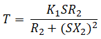
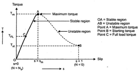
Answer: ( 3 ) Explanatory Answer: Under running conditions, the motor torque is given as: Where, R2 is rotor resistance and X2 is rotor reactance and S is the slip Below the curve between the torque and the slip
Figure 2: Torque-Slip Characteristic Curve At S = 0, T = 0. Hence the curve starts at the origin. At normal speed, S is small, hence SX2 is negligible small. Thus Torque, T ∝ S and Torque-Slip characteristics is a straight line from zero slip to slip at full load. As the slip increases further beyond full load, the torque increases and becomes maximum at S = R2/X2. As the slip increases beyond the value of slip at maximum torque, the value SX2 is much larger compared to R2 and thus . T ∝ 1/S Thus, for smaller values of slip, torque is directly proportional and for larger values of slip, it is inversely proportional.
Show Explanatory Answer
Q33. For an 8-pole induction motor supplied with power by a 6 pole Alternator at 1200 revolutions per minute, the value of motor speed at slip of 3% is ________.
- 800 RPM
- 400 RPM
- 873 RPM
- 900 RPM
Explanatory Answer: Given Speed of Alternator, N = 1200 RPM Number of Alternator poles, P = 6 Supply frequency, f = PN/120 = 60 Hz Hence, for number of 8 poles in Induction motor, the synchronous speed or speed of rotating field is: Ns = 120f/P = 900 RPM Let Nr is actual speed of motor. Thus, Percentage Slip, S % = ((Ns – Nr)/Ns) x 100 Substituting the values, we get: Nr = Ns (1-S/100) = 873 RPM.
Show Explanatory Answer
Related Posts :


Dear have you post only one MCQ in this cahp?
As some of our MCQs pages are not working well, but we are working on it and it will be live (soon)… Thanks for pointing the msg
Hello
if we have three phase ( 220 ) induction motor ( star connection ) and power supply changed to 380 3 phase
is it possible to change the motor connection to be delta connection and use 380 volt
As an Industrial Electrician for more than 40 years I remember learning these things in school in the 1970’s but almost none of this stuff is practical for what a technician needs to know to safely troubleshoot electrical problems in an industrial environment. Can you tell me when a Fuse Blows in a motor Circuit whether the motor has a grounded lead or a mechanical bind? What I want to know you can do is read schematics and be able to follow from one page to another where power or instrumentation comes from or goes to, How to wire a 220 or 480 Volt AC Motor. The Difference between 3 and 4 wire 220 VAC. Motor Starter Circuits and Winding Changeover. Questions about lighting Ballast and emergency lighting, Automatic Bus Transfer Systems, Circuit Breakers and fuse ratings. How to check voltage and power on 3 phase systems. Practical things, not theoretical.
A fuse will blow due to excess current flowing in the particular final sub-circuit because of the following;
(1) electrical over oad, (2) mechanical over load, (c) sustained overload. This is why it is necessary to carry out load analysis properly and by a qualified at installation time to avoid unnecessary over loads of this nature.
Hi, This is a very very informative post. Please add more MCQs. Thanks