Starting & Controlling of 3-Phase Motors Using Automatic Star-Delta Starter (Y-Δ)
A Star-Delta starter is an electromechanical device used to start and control the speed of a three-phase induction motor. This starter employs the star-delta (Y-Δ) method for starting the motor, which involves changing the motor’s winding connection from a Star configuration to a Delta configuration once the motor reaches a certain speed.
The Star-Delta starter includes a control circuit that typically consists of a timer, contactors, and overload relays. When the motor is started, it is initially connected in a Star configuration to reduce the starting current, which can be up to 6 times the motor’s full-load current. After the motor reaches a specific speed, the timer switches the winding connection to a Delta configuration to ensure the motor operates efficiently.
This starter is widely used in industries where high-power motors are required, such as in oil and gas, mining, and manufacturing. The star/delta starter offers several advantages, including reduced starting current, better control of inrush current, and reduced stress on the motor windings during starting. However, it also has some disadvantages, including increased cost and complexity, longer starting time, and reduced torque during starting.
In this tutorial, we will demonstrate the automatic star-delta (Y-Δ) starting method for 3-phase AC induction motors. This will include providing a schematic, power and control, PLC ladder, and wiring diagrams. We will also explain how the star-delta starter works and discuss its applications, as well as its advantages and disadvantages.
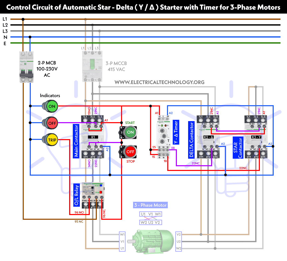
Working of the Automatic Star / Delta Starter using Timer
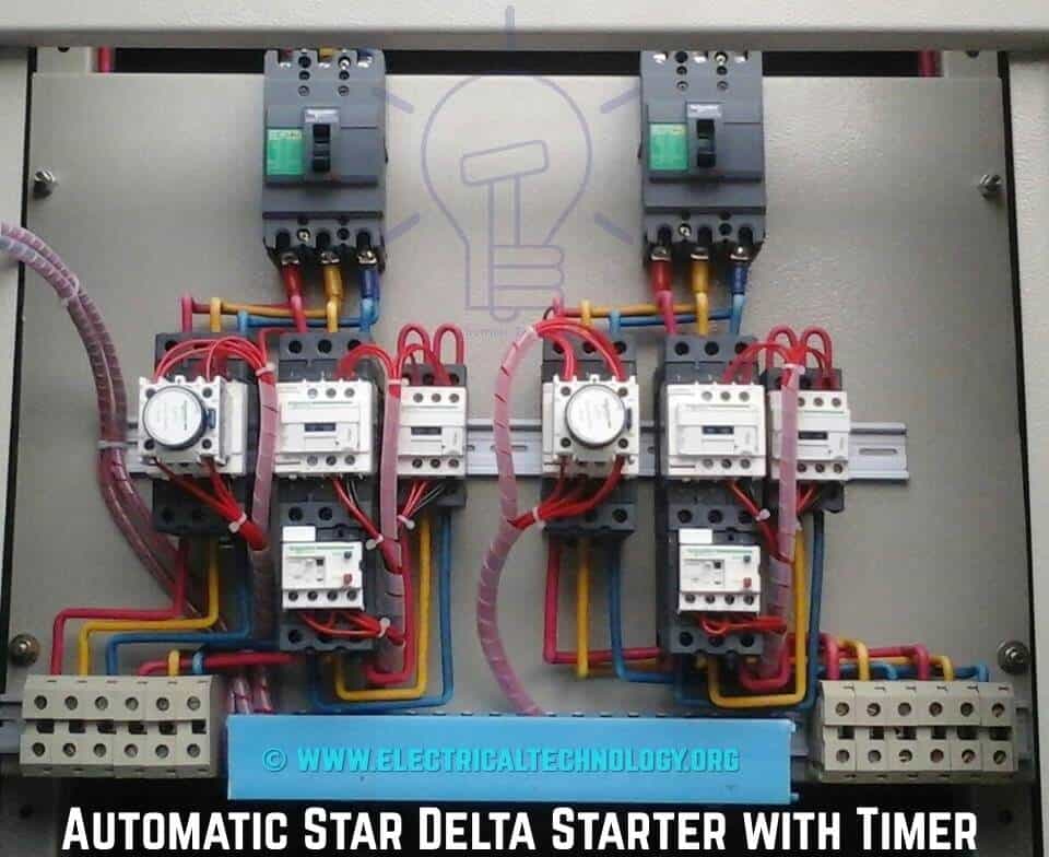
On the left-hand side, there is the main contactor with a pneumatic timer. The main contactor is always energized.
In the middle, there is the Delta contactor, which is equipped with a thermal overload for motor protection in the event that the motor exceeds the ampere rating set on the thermal overload.
On the right-hand side, there is the Star contactor, which is the first contactor to be energized with the main contactor. When the timer reaches its time limit, the Star contactor de-energizes, and the Delta contactor energizes. This allows the motor to run at full load.
Related Motor Control & Power Diagrams:
- STAR/DELTA Starter Without Timer – Power, Control & Wiring Diagrams
- Reverse/Forward Circuit for Motors using Start Delta & Timer – Power & Control Diagrams
- REV-FWD Three Phase Motor using Star/Delta Starter without Timer
Operation & Working of Automatic Y-Δ Starter
- The phase current flows from L1 to the thermal overload contact through an MCB/MCCB or general fuse, then to the OFF push button, On push button interlocking contact 2, and then to K3. The circuit is thus completed, and both contactor coil C3 and timer coil (T) are energized simultaneously. As a result, the motor winding is connected in Star, and when K3 is energized, its auxiliary open links will close, and the close links will open.
- Consequently, Contactor K1 is also energized, and the Three Phase Supply reaches the motor. Since the winding is connected in Star, each phase will receive √3 times less than the line voltage, which ensures safe motor starting. The close contact of K3 in the Delta line opens, preventing the activation of contactor 2 (K2).
- After the push button is released, Timer coil and coil 3 will receive a supply through Timer contact (Ia), Holding contact 3, and the close contact 2 of K2. When Contactor 1 (K1) is energized, the two open contacts in the line of K1 and K2 will close.
- For a specific time (generally 5-10 seconds), the motor will be connected in Star. After that, the Timer contact (T) will open (which can be adjusted by rotating the timer knob to set the time again), and as a result, Contactor 3 (K3) will turn off, and the open link of K3 (in the line of K2) will close, causing K2 to energize. When K3 is off, the star connection of the winding will also open, and K2 will close, connecting the motor winding in Delta. Contact 2 (which is in the line K3) will also open, preventing the activation of coil 3 (K3).
- Now that the motor is connected in Delta, each phase will receive full line voltage (415V), and the motor will start to run at full speed.
Related Post:
- Why Do We Need to Install a Starter with a Motor?
- Difference between Star and Delta Connections – Comparison Of Y/Δ
Wiring, Power & Control Diagrams of Star Delta Starter
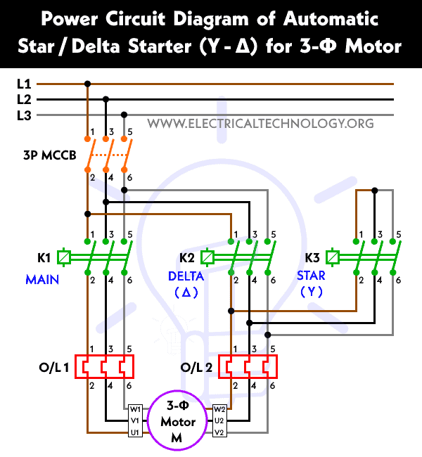
Power Diagram
Click image to enlarge
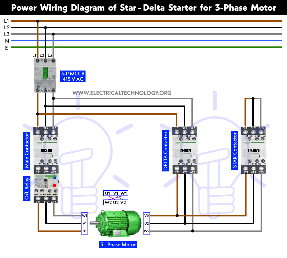
Schematic Wiring Diagram
Click image to enlarge
Control Diagram
Click image to enlarge
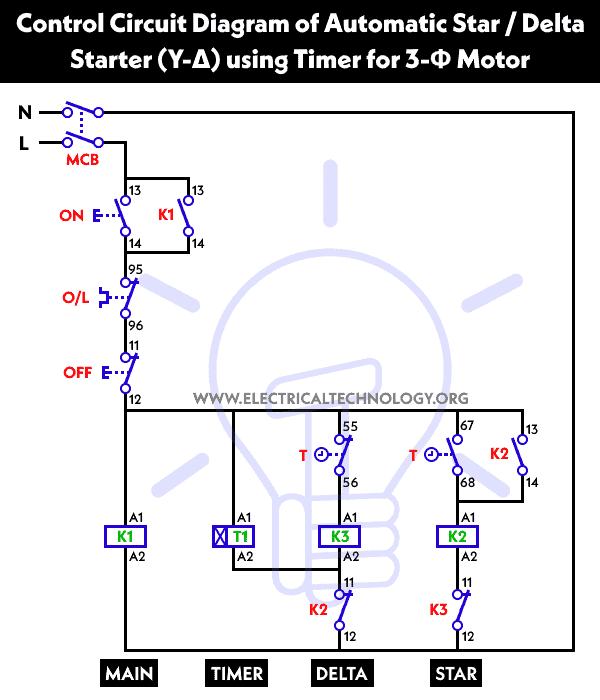
Control Circuit Diagram of Star Delta Starter with Timer
Click image to enlarge
Wiring Diagram of Y-Δ Starter using PLC

Ladder Diagram of Y-Δ Starter using PLC
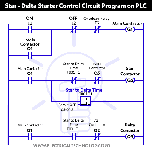
We have published an article that specifically covers the programming of a Star/Delta starter using a Programmable Logic Controller (PLC). The article includes detailed explanations and illustrations of the ladder, power, and control circuit diagrams for the setup.
Related Posts:
- Starting & Stopping of 3-Phase Motor from More than One Place – Power & Control Diagrams
- How to Start & Stop a 3-Phase Motor Using Direct-On-Line (DOL) Starter?
- Controlling of 3-Phase Motor from More than Two Places – Power & Control Diagrams
Legends and its Abbreviations:
- L1 , L2, L3 = Brown, Black, Blue ( 3 Phase Lines)
- CB / MCB / MCCB = General Circuit Breaker
- Main = Main Supply
- Y = Star
- Δ = Delta
- T = Timer
- K1, K2, K3 = Contactors
- O/L = Thermal Overload Relay
- NO = Normally Open
- NC = Normally Closed
- K1/NO = Contactor Holding Coil (Normally Open)
Advantages & Disadvantages
Advantages:
- Simple design and operation.
- Comparatively cheaper than other voltage controlling methods.
- The torque and current performance of the Y-Δ starter is good.
- It draws two times the starting current of the FLA (Full Load Ampere) of the connected motor.
- It reduces the starting current to approximately one-third compared to a DOL (Direct ON Line Starter).
Related Posts
- Automatic Sequential Motor Control Circuit – Power & Control Diagrams
- Reverse / Forward Circuit for 3-Phase Motors – Power & Control Diagrams
- Three Phase Slip Ring Rotor Starter – Control & Power Diagrams
Disadvantages
- Starting Torque is also reduced to one-third because the starter reduces the starting current to one-third of the rated current [as Line voltage is also reduced to 57% (1/√3)].
- It requires six leads or terminals for a Delta-connected motor.
- For Delta connection, the supply voltage must be the same as the rated motor voltage.
- At switching time (from Star to Delta), if the motor does not reach at least 90% of its rated speed, then the current peak may be equally high as in a Direct ON Line starter( D.O.L), thus causing harmful effects on the contactor’s contacts, making it unreliable.
- We should not use a star-delta starter if the required (application or load) torque is more than 50% of the three-phase induction motor’s rated torque.
Related Posts:
- Multispeed (2 Speeds, 2 Directions) 3-Phase Motor Power & Control Diagrams
- Multispeed (2 Speeds, 1 Direction) 3-Phase Motor Power & Control Diagrams
- Multispeed (3 Speeds, 1 Direction) 3-Phase Motor – Power & Control Diagrams
Characteristics & Features of Star-Delta Starter
- The starting current is 33% of the full load current for a star-delta starter.
- The peak starting torque is 33% of the full load torque.
- The peak starting current is 1.3 to 2.6 times the full load current.
- Star-Delta starters can be used only for low to high power three-phase induction motors.
- They have reduced starting current and torque.
- Six connection cables are needed for the motor terminal box.
- In a star/delta starter, there is a current peak and high transmission on mechanical load during the changeover from star to delta.
Applications
As we know, the main purpose of a star-delta starter is to start the three-phase induction motor in Star Connection and then switch to Delta Connection during operation.
It’s important to keep in mind that a Star-Delta starter can only be used for low to medium voltage and light starting torque induction motors. In the case of direct on-line (D.O.L) start, the current drawn by the motor is about 33% of its rated current, and the starting torque is reduced by about 25-30%.
As a result, the Star/Delta Starter is suitable only for light loads during motor starting. Otherwise, a heavy-load motor won’t start due to the low torque available during the acceleration phase while converting to the Delta connection
Related Tutorials and Resources used in Power & Control Wiring Diagrams for Motors
- Star – Delta Motor Control Circuit Using Delta – DVP 14SS2 Series PLC
- Star – Delta Motor Control Using Schneider Zelio Logic PLC Smart Relay
- Star – Delta Starter Motor Control Circuit Using S7-1200 PLC
- Automatic Star – Delta Starter Motor Control Circuit Using LOGO! V8 PLC
- Star – Delta Motor Control Circuit Using Omron PLC ZEN Programming Relay
- What is Motor Starter? Types of Motor Starters and Motor Starting Methods
- What is Soft Starter? Its Working, Diagram and Applications
- Direct Online Starter – DOL Starter Wiring Diagram for Motors
- What is a Contactor ? Types, Working and Applications
- Three Phase Motor Power & Control Wiring Diagrams
-
 Difference Between Squirrel Cage and Slip Ring (Wound) Rotor
-
 Why Don’t Bug Zappers and Fly Swatter Bats Kill Humans?
-
 Why Use VCB Circuit Breakers in HV Transmission, & Not ACB?
-
 Electric Fence – Working, Types, Protection & Installation
-
 Electromagnetic or Electromechanical Relay – Construction, Working, Types, & Applications
-
 Why Does the High-Wattage Bulb Glow Brighter in a Parallel Circuit?