Electrical Interlocking – Contactor Interlocking Control Circuit
Power and Control Circuit Diagram of Electrical Contactor’s Interlocking
What is Electrical Interlocking?
Electrical interlocking is a mechanism of electrical controls and devices designed to ensure the safe and orderly operation of electrical circuits, machinery, or equipment by preventing certain actions or conditions unless specific prerequisites are met. For example, when we need to perform a motor reverse-forward operation controlled by two contactors, only one contactor should be operational at a time to prevent damage to the circuit.
It relies on the use of logic-based controls, such as relays, contactors, and sensors, to create dependencies between different electrical components or processes.
The primary purpose of electrical interlocking is to enhance safety and prevent accidents or damage by enforcing predefined sequences of operation, ensuring that equipment or systems operate in a coordinated and controlled manner. This technique is commonly applied in industrial settings, automation systems, and power distribution networks to mitigate risks and maintain operational integrity.
In practical applications, electrical interlocking is commonly used in scenarios where multiple motors, machines, or equipment need to operate in a specific sequence or under particular conditions. By interconnecting these devices and employing logical control strategies, electrical interlocking ensures that actions occur in a safe and coordinated manner, adhering to established operational protocols. This technique is widely used in various industries, including manufacturing, automation, and power distribution, to enhance safety and system reliability.
Contactor Interlocking
Contactor interlocking is a system in which only one contactor is functional and performs a single operation at a time to prevent damage to the overall circuit. For example, in the case of a motor controlled by a star-delta starter, the motor can only run in either the star or delta configuration because the interlocking system of contactors prevents both contactors from operating simultaneously.
To interconnect the motor circuit in such a way that the second motor will not start until the first one runs, and likewise, the third motor will not run unless the second one runs, and so on (same like sequential operation of motors). This type of motor circuit connection is called interlocking.
A simple electrical interlocking control circuit diagram is shown below.
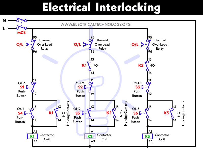
Working of Electrical Interlocking
- When we push the ON-1 button to energize the M1 Contactor (or start the M1 Motor), the circuit completes through the Fuse, the Overload relay’s trip link, OFF Push -1, and ON Push 1. Motor M1 then starts to run.
- As Contactor M1 energizes, all its normally closed (NC) contacts open, while the normally open (NO) contacts close.
- When M1 energizes, the normally open (NO) contact immediately closes, which is in parallel with ON-Push 1. This is called the Holding circuit, as it keeps the motor in the starting condition. Now, the motor will continue to run even if we release (disconnect) ON-Push 1.
- A normally open (NO) contact is also used in line 2. When M1 energizes, this link (NO M1 in line 2) also closes, causing M1 Motor to start running. Consequently, the supply also reaches ON-Push 2. If we press ON-Push 2, the second motor, M2, will start to run. Additionally, the normally open (NO) contacts of the connected contactor M2 in the circuit will also close immediately. Holding will occur through the M2 link, which is in parallel with ON-Push 2. Consequently, Motor 2 will start running.
- It’s important to note that Motor 2 will not start running until Motor 1 runs, meaning that Motor 1’s link M1 must close. Similarly, Motor 3 will not start until Motor 2 runs. In other words, Motor 3 will start running (by pressing the ON-Push for Motor 3, denoted as M3) after Motor 2 has started.
In each control circuit, fuses, circuit breakers and overload relays are connected for short circuit and overload protection, respectively.
Modification in the Electrical Interlocking Control Circuit
This is a straightforward electrical interlocking circuit, and many similar circuits are employed across various industries. The specific interlocking configuration depends on the nature of the task motors are required to perform. Consequently, creating and utilizing various interlocking circuits for different purposes is easily achievable.
This is a basic electrical interlocking circuit, and many similar circuits can be designed by using some modification in this circuit. The specific interlocking configuration depends on the nature of the task motors are required to perform. Consequently, creating and utilizing various interlocking circuits for different purposes is easily achievable. For example, let’s see the following scenario,
We can modify the operation and control of the motors in the above simple electrical interlocking control circuit diagram. For instance, if we want Motor-1 to stop when Motor-3 starts running, we can use a Normally Closed (NC) link of K3 in line 1. When Contactor K3 energizes and Motor-3 starts running, the Normally Closed (NC) link of Motor-1 connected in line 1 will immediately open (after K3 Contactor energizes). This action de-energizes the K1 contactor, causing Motor-1 to stop.
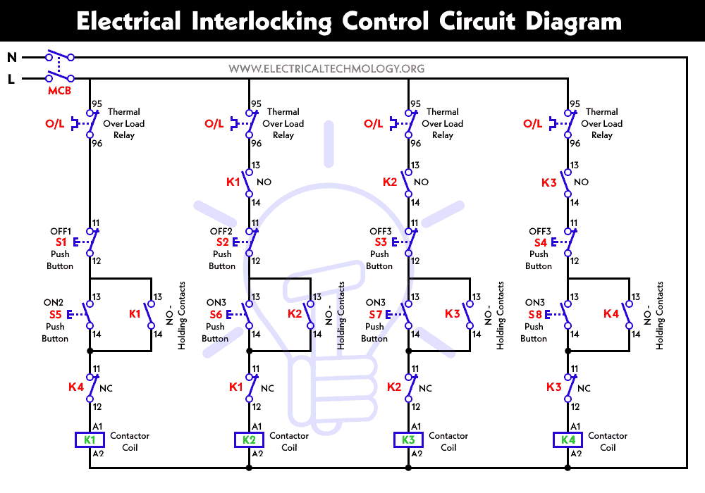
With a few minor modifications, we can configure the above electrical interlocking control circuit to start and run each motor individually as shown in the following control diagram.
Power & Control Wiring Diagrams of Interlocking
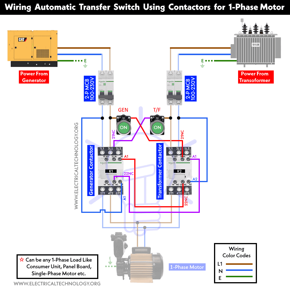
Interlocking for Single Phase Motor Connected to 2 Power Supplies.
The automatic ATS wiring diagram below illustrates the connection of a single-phase motor to two different power supply sources: the main supply and a backup generator. The two contactors in this setup are electrically interlocked, allowing only one contactor to be operational at any given time, whether it’s the contactor for the main supply or the contactor for the generator supply. This arrangement effectively prevents damage to connected appliances.
Interlocking for Three-Phase Motor Designed for Two Directions
The following diagram illustrates the connection of a three-phase motor through a Direct Online starter. This connection offers both forward and reverse operations using a DOL starter, which is based on contactors and a thermal overload relay. Both contactors (1 and 2) are interlocked, ensuring that only one of them can operate at any given time. Contactor 2 is used for forward operation, while contactor 1 is used for reverse operation.
Thanks to the interlocking feature, as this arrangement effectively prevents short circuits and serious damage to the connected machinery, thanks to the interlocking feature.

For further interlocking tutorials and wiring diagrams, we have used the same mechanism of holding and interlocking for Two-Speed, One-Direction, Two-Speed, Two-Direction, Reverse-Forward Motor Control, Sequential Operation of Motors and Star-Delta Starter using Timer for three-phase induction motors.
Related Posts:
- How to Wire 8-PIN Relay for Holding or Latching Circuit?
- How to Wire 11-PIN Relay for Interlocking and Holding Circuits?
- How to Wire 14-PIN Relay for Holding or Latching Circuit?
- Automatic Phase Reverse Protection Using Contactors & Relay
- Types of Electrical Drawing and Diagrams
- Three Phase Motor Power & Control Wiring Diagrams


Thanks information
keep going
where is the interlocking in your circuit diagram? i am not found out any n/o in your diagram.
i think there are mistakes in first image:
1) in second line must be m1/nc and not m1/no
2)in third line must be m2/nc instead of m2/no
I need interlocking circuit for electrical interlocking between three incomer feeders and two bus coupler feeders
awaiting supports
thanks
Best Regards
Tariq
This control diagram is sequence operation not for interlock
can you provide by interlock diagram
Here it is: Electrical Interlock Control & Power Diagram
Thank you so much for the technical information.
There is a mistake in n open and close contact
Thaanks……………
In this interlocking drawing L1 Phase power then what is L2 ?
This system is very simple. I thanking to you explain this system.
i have to find this
Thanks it is a good explanation and it is easy to understand
Your explanation is awesome and easy to understand thanks. Great job.
Please explain interlock with 2 pump running and 1 pump should be not running. (Total 3pumps)