Star – Delta Starter Motor Control Circuit Using S7-1200 PLC
Automatic Star – Delta Starter Motor Control Circuit Using Siemens S7-1200 PLC
Star-delta starter motor control circuits are widely used in industrial applications to control the starting of three-phase electric motors. This type of circuit is used to reduce the starting current of the motor and thus prevent damage to the motor and its connected equipment. In this technical article, we will discuss how to implement a star-delta starter motor control circuit using the S7-1200 PLC.
The SIMATIC S7-1200 is a type of programmable logic controller (PLC) manufactured by Siemens. It is a compact and modular PLC that is designed for use in a wide range of industrial automation and control applications.
In the following post, we will show how to control and operate a three phase induction motor using star-delta starter with the help of S7-1200 PLC?
Related Pots:
- Automatic Star – Delta Starter Motor Control Circuit Using LOGO! V8 PLC
- Automatic Star-Delta Starter using Timer – Power, Control & Wiring Diagrams
Schematic, Control, Ladder & Wiring Diagrams
The wiring diagram for the automatic star-delta starter using S7-1200 is shown below:
Click image to enlarge
Power Diagram

Schematic Diagram

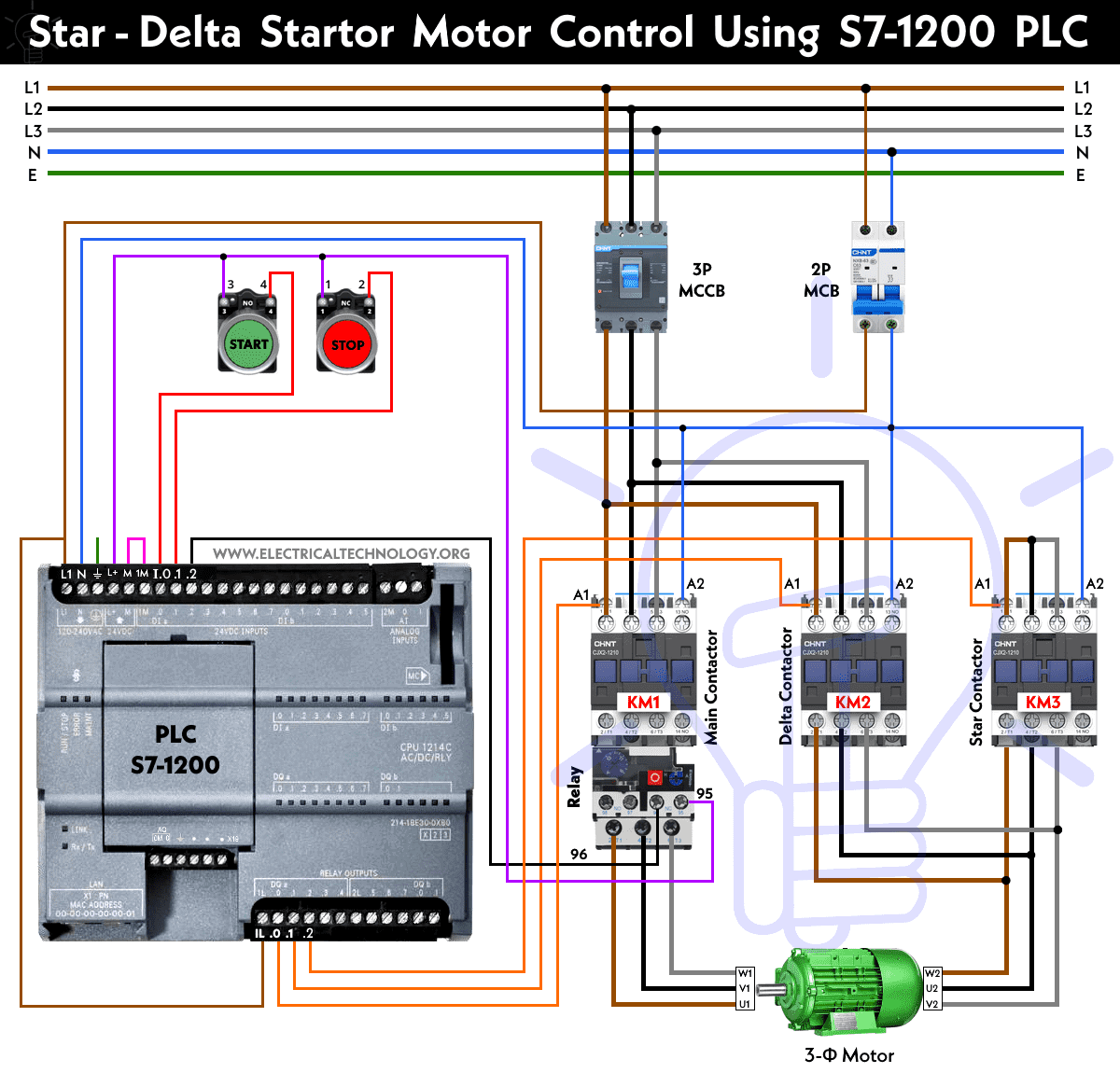
As shown in the power and wiring diagrams, the star-delta starter motor control circuit consists of three contactors namely KM1 (main contactor) KM2 (delta contactor) and KM3 (star contactor) a timer based PLC like S7-1500, LOGO! V8 and S7-200 or S7-1200 PLC.
The contactors are used to switch between the star and delta configurations of the motor. The timer is used to delay the switching from the star to the delta configuration to allow the motor to reach a stable operating state. The PLC is used to control the switching of the contactors and the timing of the circuit.
Wiring & Control Circuit

As shown, the three contactors K1, K2 and K3 are connected to the output terminal of S7-1200 PLC. push buttons (ON and OFF) and thermal overload relay with main contactor K1 are connected to the input terminals viz I0.0, I0.1 and I0.2 respectively. The L1, N and E is connected to the 230V AC Line, Neutral and protective Earth using 2 Poles MCB. All the contactors are connected via 3 Poles MCCB via L1, L2 and L3.
The (A1) and (A2) terminals in all three contactors are connected to the the output terminal of PLC via Q0.0, Q0.1, Q0.2 and Neutral wire respectively. The terminal of thermal overload relay (95 & 96) are connected to the I0.2 and L+ from the PLC.
Related Posts:
- STAR/DELTA Starter Without Timer – Power, Control & Wiring Diagrams
- Reverse/Forward Circuit for Motors using Start Delta & Timer – Power & Control Diagrams
Programming & Ladder Diagram

To implement the star-delta starter motor control circuit using the S7-1200 PLC, we will need to follow the following steps:
- Connect the power supply to the PLC and configure the necessary input and output modules.
- Connect the contactors to the output modules of the PLC. The contactors should be connected such that when the star contactor is energized, the motor is connected in the star configuration and when the delta contactor is energized, the motor is connected in the delta configuration.
- Configure the PLC program according to the logic control circuit as shown above to control the switching of the contactors. The program should include logic to energize the main contactor and then star contactor first, allow the motor to reach a stable operating state, and then switch to the delta configuration by energizing the delta contactor.
- Configure the timer in the PLC program to delay the switching from the star to the delta configuration. The delay time should be set to allow the motor to reach a stable operating state before switching to the delta configuration.
- Test the circuit to ensure that it is working as intended. The test should include verifying that the motor is starting in the star configuration, switching to the delta configuration after a delay, and running smoothly in the delta configuration.
Summary
Implementing a star-delta starter motor control circuit using the S7-1200 PLC is a relatively simple process that requires basic knowledge of PLC programming and electrical wiring. By following the steps outlined in this technical article, you can create a reliable and efficient motor control circuit that can be used in a variety of industrial applications.
Related Power & Control Wiring Diagrams for Motors
- Star/Delta Starter Using a Programmable Logic Controller (PLC) – Ladder & Wiring Diagrams.
- Automatic Sequential Operations of Motors – Power, Control, PLC & Wiring Circuits
- Reverse / Forward Circuit for 3-Phase Motors – Power & Control Diagrams
- Three Phase Slip Ring Rotor Starter – Control & Power Diagrams
- Starting & Stopping of 3-Phase Motor from More than One Place – Power & Control Diagrams
- ON / OFF Three-Phase Motor Circuit – Schematic Power, Control & Wiring Diagrams
- Controlling of 3-Phase Motor from More than Two Places – Power & Control Diagrams
- Multispeed (2 Speeds, 2 Directions) 3-Phase Motor Power & Control Diagrams
- Multispeed (2 Speeds, 1 Direction) 3-Phase Motor Power & Control Diagrams
- Multispeed (3 Speeds, 1 Direction) 3-Phase Motor – Power & Control Diagrams


