Star – Delta Motor Control Circuit Using Omron PLC ZEN Programming Relay
How to Wire Automatic Star – Delta Control Circuit For Motors Using Omron ZEN Programming Relay?
Star Delta Control is a widely used technique for reducing the starting current of a three-phase induction motor. This technique involves connecting the motor in a star connection during the starting process and then switching to a delta connection once the motor has reached full speed. In this article, we will discuss how to implement a Star Delta Control using Omron PLC ZEN Programming Relay.
In the following post, we will show how to run and control a three phase induction motor using star delta starter using the ZEN programmable Relay. (We have used 10C1AR-A-V2 (100-230V AC) relay in this tutorial).
Related Posts:
- Star – Delta Starter Motor Control Circuit Using S7-1200 PLC
- Automatic Star – Delta Starter Motor Control Circuit Using LOGO! V8 PLC
Hardware & Components Required
The following hardware components are required to implement the automatic star-delta starter:
- ZEN Programable Relay – ZEN V2, ZEN PA, ZEN 10C etc.
- 3-Phase Induction Motor
- 3P MCCB
- 2P MCB
- 2 Nos of NC Push Buttons Switches
- 3 Nos of Magnetic Contactors
- Thermal Overload Relay
- 400-480V Three Phase supply
- 230V Single Phase Supply
Power, Wiring & Ladder Control Diagrams
Wiring Diagram
Click image to enlarge

In the above wiring diagram,
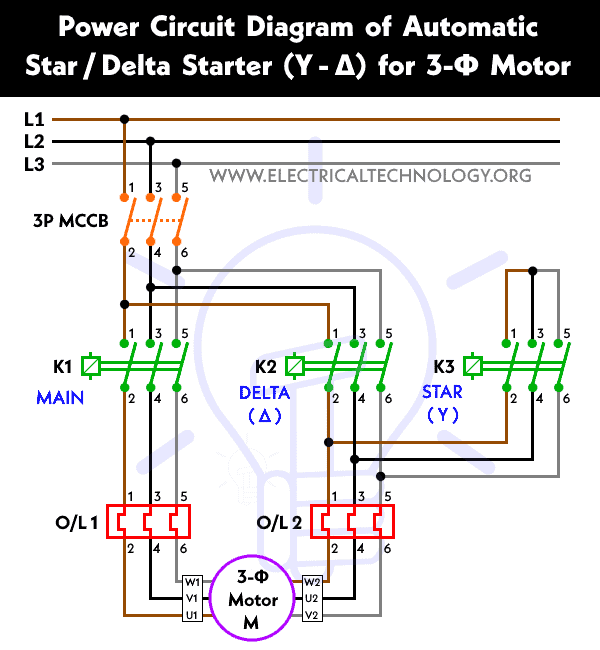
- Contactor KM1 is used as main contactor to switch from star in the initial stage to the delta for safe operation.
- Contactor KM2 is used to run the motor in delta configuration
- Contactor KM1 is used to run the motor in star configuration.
Power Diagram
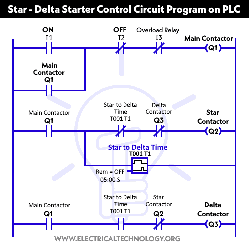
Ladder Control Diagram
Related Posts:
- Star Delta Motor Control Using Schneider Zelio Logic PLC Smart Relay
- Star – Delta Motor Control Circuit Using Delta – DVP 14SS2 Series PLC
Programming Steps
To create a Star Delta Motor Control Circuit using Omron PLC Zen Programming Relay, you can follow these steps:
Step 1: Create a New Project
Create a new project in Omron’s CX-Programmer software (or (ZEN-SOFT01-V4) and select the appropriate PLC model. Once the project is created, create a new ladder diagram program.
Step 2: Create the Control Section
The control section is responsible for controlling the switching between the star and delta configurations. In this section, a timer (based on PLC) is used to delay the switching from the star to the delta configuration. This delay allows the motor to reach full speed before the circuit switches to the delta configuration. To create the control section, follow these steps:
- Create a timer function block.
- Set the timer value to the required delay time.
- Connect the output of the timer to a contactor & relay function block.
- Set the relay function block to activate the delta contactor.
Step 3: Create the Star Section
The star section (magnetic contactor KM3) is responsible for connecting the motor in a star configuration. In this section, three contactors and relays function blocks are used to connect the motor to the power supply. Each relay function block is responsible for connecting one phase of the motor to the supply. A fourth relay function block is used to connect the neutral wire to the supply. To create the star section, follow these steps:
- Create three relay function blocks.
- Connect the outputs of the relay function blocks to the contactors.
- Set the relay function blocks to activate the contactors.
- Create a fourth relay function block.
- Connect the output of the fourth relay function block to the neutral contactor.
- Set the fourth relay function block to activate the neutral contactor.
Step 4: Create the Delta Section
The delta section is responsible for connecting the motor in a delta configuration. In this section, three relay function blocks are used to connect the motor to the power supply. Each relay function block is responsible for connecting two phases of the motor to the supply. To create the delta section, follow these steps:
- Create three relay function blocks.
- Connect the outputs of the relay function blocks to the contactors.
- Set the relay function blocks to activate the contactors.
Step 5: Create the Main Program
The main program is responsible for calling the control section, the star section, and the delta section. It also sets the initial state of the relays to ensure that the motor starts in the star configuration. To create the main program, follow these steps:
- Create a main program.
- Call the control section.
- Call the star section.
- Set the initial state of the star relays to activate.
- Call the delta section.
- Set the initial state of the delta relays to deactivate.
Once you have completed the programming, you can download the program to the Omron PLC Zen Programming Relay and connect it to your motor to control its operation. It is important to ensure that all wiring and connections are correct and properly insulated to prevent accidents or damage to the motor or PLC.
Related Power & Control Wiring Diagrams for Motors
- Star/Delta Starter Using a Programmable Logic Controller (PLC) – Ladder & Wiring Diagrams.
- Automatic Star-Delta Starter using Timer – Power, Control & Wiring Diagrams
- STAR/DELTA Starter Without Timer – Power, Control & Wiring Diagrams
- Reverse/Forward Circuit for Motors using Start Delta & Timer – Power & Control Diagrams
- Automatic Reverse – Forward Motor Control Circuit Using Omron CP2E PLC
- Automatic Sequential Operations of Motors – Power, Control, PLC & Wiring Circuits
- Reverse / Forward Circuit for 3-Phase Motors – Power & Control Diagrams
- Three Phase Slip Ring Rotor Starter – Control & Power Diagrams
- Starting & Stopping of 3-Phase Motor from More than One Place – Power & Control Diagrams
- ON / OFF Three-Phase Motor Circuit – Schematic Power, Control & Wiring Diagrams
- Controlling of 3-Phase Motor from More than Two Places – Power & Control Diagrams
- Multispeed (2 Speeds, 2 Directions) 3-Phase Motor Power & Control Diagrams
- Multispeed (2 Speeds, 1 Direction) 3-Phase Motor Power & Control Diagrams
- Multispeed (3 Speeds, 1 Direction) 3-Phase Motor – Power & Control Diagrams
- Even More Motor Control Circuits and Diagrams


