Automatic Star – Delta Starter Motor Control Circuit Using LOGO! V8 PLC
How to Wire Automatic Star – Delta Starter Control Circuit For Motors Using Siemens LOGO! V8 PLC
The star-delta starter is an electrical motor control circuit that reduces the starting current and torque of the motor. This is achieved by initially connecting the motor winding in star configuration and then changing to delta configuration once the motor is up to speed. In this article, we will discuss how to implement an automatic star-delta starter for motor control using LOGO! V8 PLC.
LOGO! V8 by Siemens is a Universal Logic Module used for module control and general purpose compact PLC, specialized in addressing installation and domestic tasks. Its purpose is to assist in the transition from traditional relay and contactor logic, which were in use prior to the development of PLCs. It has replaced the old relay models, and the latest model can handle up to 20 digital inputs and outputs, and 8 analog I/O. Moreover, it supports and expands additional I/O communication modules.
Related Pots:
- Star – Delta Starter Motor Control Circuit Using S7-1200 PLC
- Automatic Star-Delta Starter using Timer – Power, Control & Wiring Diagrams
In the following post, we will show how to run and control a three phase induction motor using star delta starter with the help of LOGO! V8 PLC.
Hardware Requirements
The following hardware components are required to implement the automatic star-delta starter:
- Siemens LOGO! V8 PLC
- Motor Contactor
- Overload Relay
- Auxiliary Contact Block
- Push Buttons
- Selector Switches
- Terminal Blocks
- Power Supply Unit
- Three Phase Motor
Schematic, Control, Ladder & Wiring Diagrams
The wiring diagram for the automatic star-delta starter using LOGO! V8 is shown below:
Click image to enlarge
![]()
Circuit Diagram
![]()
Power Diagram

Schematic Circuit Diagram
![]()
In the power and wiring diagrams, L1, L2, and L3 represent the three-phase power supply, and W, V, and V represent the three motor terminals. The motor contactor is used to switch the motor between star and delta configurations. The overload relay protects the motor from overcurrent and short circuits. The push buttons and selector switches are used to control the motor starter.
The main contactor KM1 with associated thermal overload relay (95 & 96) and KM2 (Delta) and KM3 (Star) contactors are connected to the three phase lines L1, L2 & L3 via three pole MCCB. The LOGO! V8 PLC is connected to both 230V AC via two pole MCB and 24V DC supply. The output of the PLC Q1, Q2 and Q3 are connected to the three contactors (A1) and the the (A2) terminals of the contactors are connected to the Neutral.
Related Posts:
- STAR/DELTA Starter Without Timer – Power, Control & Wiring Diagrams
- Reverse/Forward Circuit for Motors using Start Delta & Timer – Power & Control Diagrams
Programming & Ladder Diagram
The LOGO! V8 PLC is programmed using the LOGO! Soft Comfort software. The following program logic is used to implement the automatic star-delta starter:
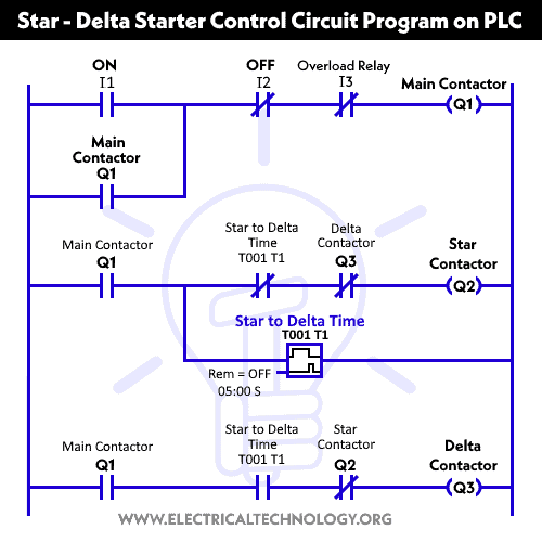
In the program logic, I1 is the input for the start push button, I2 is the input for the stop push button, and I3 is the input for the selector switch. Q1, Q2 and Q3 are the output for the Main Contactor “KM1”, Delta Contactor “KM2” and Star Contactor “KM3 respectively.
The overload relay in KM1 contactor, KM2 and KM3 contactors are connected to the common of Q1, Q2 and Q3 from LOGO! V8, 24VDC supply and 230V AC via two pole MCB.
Testing the Automatic Star-Delta Starter After completing the wiring and programming, the automatic star-delta starter can be tested by following these steps:
- Ensure that the power supply is switched off.
- Connect the motor to the motor terminals of the starter.
- Switch on the power supply.
- Set the selector switch to the star position.
- Press the start push button.
- The motor should start running in the star configuration.
- Wait for the motor to reach the desired speed.
- Set the selector switch to the delta position.
- The motor should now switch to the delta configuration.
- Press the stop push button to stop the motor.
Summary:
Implementing an automatic star-delta starter for motor control using LOGO! V8 PLC is a straightforward process. By following the wiring diagram and program logic, the starter can be easily configured and tested. The benefits of using an automatic star-delta starter include reduced starting current and torque, which can help to prolong the life of the motor and improve energy efficiency.
Related Power & Control Wiring Diagrams for Motors
- Star/Delta Starter Using a Programmable Logic Controller (PLC) – Ladder & Wiring Diagrams.
- Automatic Sequential Operations of Motors – Power, Control, PLC & Wiring Circuits
- Reverse / Forward Circuit for 3-Phase Motors – Power & Control Diagrams
- Three Phase Slip Ring Rotor Starter – Control & Power Diagrams
- Starting & Stopping of 3-Phase Motor from More than One Place – Power & Control Diagrams
- ON / OFF Three-Phase Motor Circuit – Schematic Power, Control & Wiring Diagrams
- Controlling of 3-Phase Motor from More than Two Places – Power & Control Diagrams
- Multispeed (2 Speeds, 2 Directions) 3-Phase Motor Power & Control Diagrams
- Multispeed (2 Speeds, 1 Direction) 3-Phase Motor Power & Control Diagrams
- Multispeed (3 Speeds, 1 Direction) 3-Phase Motor – Power & Control Diagrams


