Automatic Sequential Operations of Motors – Power, Control, PLC & Wiring Circuits
How to Run Motors in Sequence? Power, Control, PLC & Wiring Diagrams
A Sequential Motor Control Circuit is an electrical circuit designed to control the operation of motors in a sequential manner. The circuit is typically composed of a combination of control devices such as contactors, timers, relays, and sensors. It prevents electric motors from starting simultaneously and ensures that each motor operates in a specific sequence for a particular purpose.
Working of Sequential Motor Control Circuit
The working of a sequential motor control circuit is relatively simple. The control circuit first activates the first motor in the sequence by sending a signal to the associated starter, contactor and relay. Once the relay receives the signal, it switches on the power to the motor, causing it to start running.
When the first motor reaches a specific set point or condition, it sends a signal to the control circuit to switch off the power to the first motor and activate the second motor in the sequence. This signal can be generated by a timer or a sensor that detects the first motor’s state.
Once the second motor receives the signal, the associated relay switches on the power, causing the motor to start running. This process continues until all the motors in the sequence have been activated and are running.
In the following post, we will show the Wiring, Power, Control and PLC diagram of sequential control circuit for three phase motors.
Wiring Diagram of Control Unit for 3-Φ Motors Operation in Sequence
This sequential circuit diagram is designed to operate three motors in sequence using ON and OFF buttons to control automatically the starting and stopping operation of each three phase motor with the help of timers.
Click image to enlarge

In the power circuit diagram, each motor is connected to a separate contactor with thermal overload relay. Two timers (T1 & T2) are used with M1 and M2.
In this arrangement, the coil of first Timer “T1” is connected in parallel with the coil of Contactor “KM2”, while the timer coil “T1” is in series with the normally closed contact of “KM2”. As a result, when Contactor “KM2” is energized, the timer will be disconnected from the power supply, but Contactor “KM1” will remain active.
The automatic operation of the circuit is as follow.
- 3-Φ Motor “M1” is controlled by a set of push buttons, including an “ON” and “OFF” button.
- Three phase Motor 2 “M2” is controlled by the Timer “T1” and connected in series to the ON button.
- 3-Phase Motor 3 “M3” is controlled by the Timer “T2” and connected in series with ON button.
Wiring Diagram of Sequential Operation of 3-Phase Motors
Click image to enlarge

Power Diagram of 3-Φ Motors Running in Sequence
Click image to enlarge

Control Diagram of 3-Φ Motors Operation in Sequence
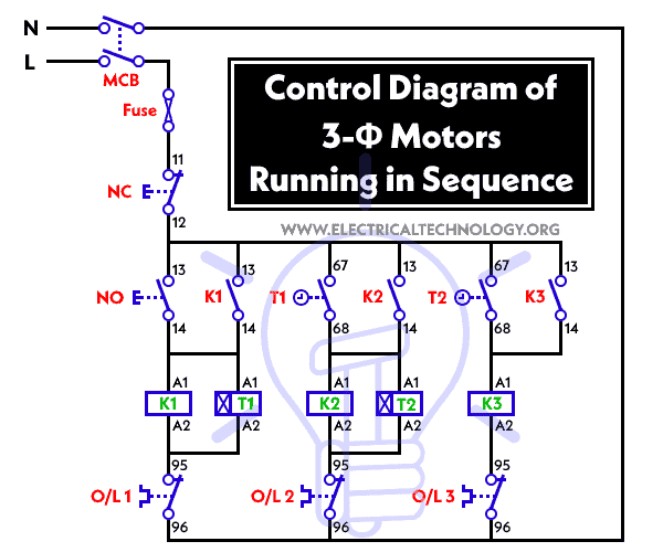
Operation of Control Circuit for Motors Running in Sequence

The sequence of operation of the three phase motors is as follow:
- The operation of Motor “M2” and Motor “M3” is dependent on the running status of Motor “M1”.
- Motor “M2” can only run when Motor “M1” is already in operation.
- Motor “M3” can only operate when both Motor “M1” and Motor “M2” are already running.
Motor “M1” = Pressing the ON button closes the contacts of contactor “K1”, causing Motor “M1” to start operating. At the same time, the coil of Timer “T1” is energized and begins counting time.
Motor “M2” = Once Timer “T1” reaches the preset time, its normally open contact closes, supplying power to contactor “K2” and causing Motor M2 to start operating. At this point, the normally closed contacts of contactor K2 opens, de-energizing the Timer “T1” coil, while the normally open contacts of contactor “K2” closes, allowing contactor “K2” to remain active. The coil of Timer “T2” is also energized and begins counting.
Motor “M3” = When Timer “T2” reaches the preset time, Contactor “K3” is energized, causing Motor M3 to start operating. Timer coil “T2” is then disconnected from the power supply.
Related Posts:
- Automatic Star – Delta Starter Motor Control Circuit Using LOGO! V8 PLC
- Star – Delta Starter Motor Control Circuit Using S7-1200 PLC
3-Φ Motor’s Sequential Control Circuit Program on PLC
The PLC program operates according to the following sequence:
- Pressing the “ON” button will turn on input “X0”, closing the circuit and activating output “Y0”. This will energize contactor coil “K1” and start motor “M1”, while Timer “T1” begins counting.
- When “T1” counts to 10 seconds, output “Y1” will activate, and Timer “T2” will start counting. At this point, contactor “K2” will close, and motor “M2” will start operating.
- Similarly, when T2 counts to the preset time of 10 seconds, the PLC will activate output “Y2”, and motor “M3” will start working.
- Pressing input “X1” will disable output “Y0”, turning off “Y1” and “Y2”. The operated will end and the program will then return to its initial state.
Abbreviations:
- L1, L2, L3 = Brown, Black, Blue (3 Phase Lines)
- N & E = Neutral and Earth
- M1, M2, M3 = Three Phase Motors
- CB/MCB/MCCB = General Circuit Breaker
- Main = Main Supply
- T1 & T2 = Timer
- K1, K2, K3 = Contactors
- O/L = Thermal Over Load Relay
- NO = Normally Open
- NC = Normally Closed
Applications of Sequential Motor Control Circuit
Sequential motor control circuits have a wide range of applications in various industries. The following are some common applications of sequential motor control circuits:
- Conveyor Systems: Sequential motor control circuits are widely used in conveyor systems to control the movement of materials. The circuit ensures that each motor is activated in sequence to move the material along the conveyor.
- Pump Systems: In pump systems, sequential motor control circuits are used to control the flow of liquids or gases. The circuit activates each pump in sequence to ensure a smooth and efficient flow of fluids.
- HVAC Systems: HVAC (Heating, Ventilation, and Air Conditioning) systems require precise control of multiple components, including motors. Sequential motor control circuits are used to ensure that each motor is activated in the correct sequence to achieve optimal performance.
- Manufacturing Processes: Sequential motor control circuits are used in various manufacturing processes, such as assembly lines, to control the movement of materials and machinery.
- Industrial Automation: In industrial automation, sequential motor control circuits are used to control the operation of machines and equipment in a precise sequence to ensure maximum efficiency and productivity.
Related Power & Control Wiring Diagrams for Motors
- Automatic Star-Delta Starter using Timer – Power, Control & Wiring Diagrams
- STAR/DELTA Starter Without Timer – Power, Control & Wiring Diagrams
- Star/Delta Starter Using a Programmable Logic Controller (PLC) – Ladder & Wiring Diagrams.
- Reverse/Forward Circuit for Motors using Start Delta & Timer – Power & Control Diagrams
- Reverse / Forward Circuit for 3-Phase Motors – Power & Control Diagrams
- Three Phase Slip Ring Rotor Starter – Control & Power Diagrams
- Starting & Stopping of 3-Phase Motor from More than One Place – Power & Control Diagrams
- ON / OFF Three-Phase Motor Circuit – Schematic Power, Control & Wiring Diagrams
- Controlling of 3-Phase Motor from More than Two Places – Power & Control Diagrams
- Multispeed (2 Speeds, 2 Directions) 3-Phase Motor Power & Control Diagrams
- Multispeed (2 Speeds, 1 Direction) 3-Phase Motor Power & Control Diagrams
- Multispeed (3 Speeds, 1 Direction) 3-Phase Motor – Power & Control Diagrams


level water how to connect
Please add more circuits like this. Thanks