Star – Delta Motor Control Circuit Using Delta – DVP 14SS2 Series PLC
How to Wire Automatic Star – Delta Control Circuit For Motors Using DVP-14SS PLC?
In industrial automation, the control of motor circuits is essential for various applications such as conveyor belts, pumps, compressors, and other equipment that require mechanical motion. One of the most popular motor control techniques is the star-delta motor control circuit. This circuit allows the motor to start in a low voltage configuration, which reduces the inrush current and protects the motor from damage. In this article, we will discuss the star-delta motor control circuit and how to implement it using the DVP-14 SS2 Delta PLC with three contactors.
Star-Delta Motor Control Circuit
The star-delta motor control circuit is a method of starting a three-phase induction motor. In this circuit, the motor is initially connected in a star configuration, which allows it to start with a low current draw. After the motor reaches a certain speed, the connection is switched to a delta configuration to provide full voltage to the motor. This process reduces the inrush current during the starting phase, which can be up to six times the full load current.
The star-delta motor control circuit consists of three contactors, a timer relay, and a PLC. The three contactors are used to switch the motor connection between the star and delta configurations. The timer relay is used to provide a delay between the start and stop signals, which allows the motor to reach the desired speed before switching to the delta configuration. The PLC is used to control the contactors and the timer relay based on the input signals.
DVP-14 SS2 Delta PLC
The DVP-14 SS2 Delta PLC is a programmable logic controller that is commonly used in industrial automation. It has a compact design, high-speed processing, and a variety of communication options. It also has a built-in digital input and output ports, which can be used to control the contactors and timer relay in the star-delta motor control circuit.
Related Posts:
- Star – Delta Starter Motor Control Circuit Using S7-1200 PLC
- Automatic Star – Delta Starter Motor Control Circuit Using LOGO! V8 PLC
Hardware Requirements
To implement the Star-Delta Motor Control Circuit using Delta DVP-14SS2 PLC, the following hardware components are required:
- Delta DVP-14SS or 14SS2 PLC
- Three-phase induction motor
- 1-Phase & 3-Phase power supply
- 24V DC Supply
- Three-phase contactors
- Single phase & three-phase circuit breakers
- 2 Nos of NC Push Buttons Switches
- Thermal Overload Relay
Wiring, Power & Ladder Control Diagrams
Wiring Diagram
Click image to enlarge

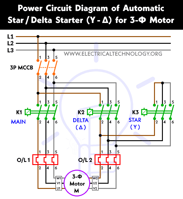
Power Diagram
Ladder Logic Control Diagram

Related Posts:
- Star – Delta Motor Control Circuit Using Omron PLC ZEN Programming Relay
- Star Delta Motor Control Using Schneider Zelio Logic PLC Smart Relay
Programming Steps
To implement the star-delta motor control circuit using the DVP-14 SS2 Delta PLC with three contactors, we need to create a ladder logic program. The program should include the following steps:
- Wire the hardware components to the PLC according to the wiring diagram given above.
- Open the WPLSoft software on your desktop or laptop.
- In the dialogue box, select the proper model no. of PLC and click on Ok.
- Two windows will appear on the screen, namely Instruction list mode and Ladder diagram mode. Choose the Ladder diagram mode and maximize the window.
- Write the Relay Ladder Logic program for Star-Delta starter as shown in power and control diagrams.
- Compile the program using Ctrl + F7. If there are any errors, correct the program.
- Write the program to PLC using Ctrl + F8, and check the output.
- To observe the output on your laptop/desktop itself, select the simulator mode, then online mode, and finally run the program using Ctrl + F11.
Working of the Circuit
Step 1: Start Signal
The start signal is a push-button switch that is used to initiate the motor starting sequence. When the start signal is activated, contactor KM1 should be switched to the star configuration (Contactor KM3), and the timer relay should be activated.
Step 2: Timer Relay
The timer relay is used to provide a delay between the start and stop signals. The delay time should be set to allow the motor to reach the desired speed before switching to the delta configuration. When the timer relay is activated, it should start counting down from the set delay time.
Step 3: Delta Configuration
After the delay time has elapsed, contactors KM1 and KM3 should be switched to the delta configuration (KM3), which provides full voltage to the motor. Contactors KM1 and KM2 should remain in the delta configuration until the stop signal is activated.
Step 4: Stop Signal
The stop signal is a push-button switch that is used to stop the motor. When the stop signal is activated, contactors KM1and KM2 should be switched back to the star configuration, and the timer relay should be deactivated.
Step 5: Emergency Stop Signal
The emergency stop signal is a push-button switch that is used to stop the motor in case of an emergency. When the emergency stop signal is activated, all three contactors (KM1, KM2 and KM3) should be opened to stop the motor immediately.
Related Power & Control Wiring Diagrams for Motors
- Star/Delta Starter Using a Programmable Logic Controller (PLC) – Ladder & Wiring Diagrams.
- Automatic Star-Delta Starter using Timer – Power, Control & Wiring Diagrams
- STAR/DELTA Starter Without Timer – Power, Control & Wiring Diagrams
- Reverse/Forward Circuit for Motors using Start Delta & Timer – Power & Control Diagrams
- Reverse / Forward Circuit for 3-Phase Motors – Power & Control Diagrams
- Reverse Forward Motor Control Circuit Using PLC – ZEN Programming Relay
- Reverse Forward Motor Control Circuit Using Mitsubishi FX Series PLC
- Automatic Reverse Forward Motor Control Using S7-1200 PLC
- Automatic Reverse – Forward Motor Control Circuit Using Omron CP2E PLC
- Automatic Sequential Operations of Motors – Power, Control, PLC & Wiring Circuits
- Three Phase Slip Ring Rotor Starter – Control & Power Diagrams
- Starting & Stopping of 3-Phase Motor from More than One Place – Power & Control Diagrams
- ON / OFF Three-Phase Motor Circuit – Schematic Power, Control & Wiring Diagrams
- Controlling of 3-Phase Motor from More than Two Places – Power & Control Diagrams
- Multispeed (2 Speeds, 2 Directions) 3-Phase Motor Power & Control Diagrams
- Multispeed (2 Speeds, 1 Direction) 3-Phase Motor Power & Control Diagrams
- Multispeed (3 Speeds, 1 Direction) 3-Phase Motor – Power & Control Diagrams