Star – Delta Starter Using Different PLCs – Wiring and Ladder Diagram
Automatic Star – Delta Starter for Motor Control Using Different PLCs
An automatic Star Delta starter is a device that automatically controls the switching of an electric motor from the Star mode to the Delta mode. This switching is essential to reduce the inrush current that occurs during the starting of the motor. In today’s post, we will show how to program and control a three phase induction motor in star delta using PLC with wiring and ladder diagrams.
Related Posts:
- Star – Delta Motor Control Circuit Using Delta – DVP 14SS2 Series PLC
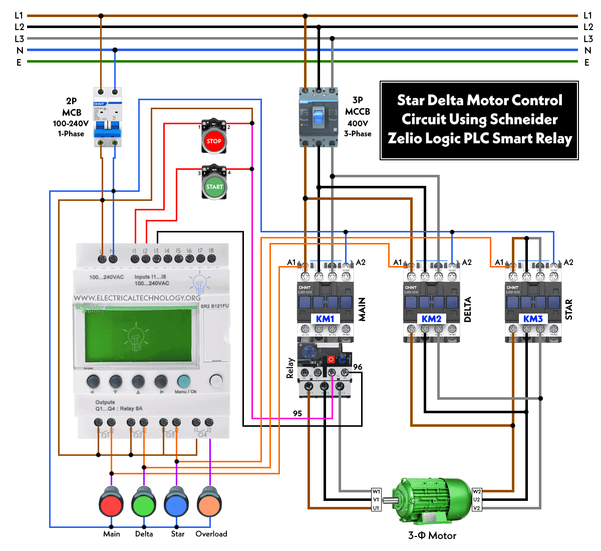
- Star – Delta Motor Control Using Schneider Zelio Logic PLC Smart Relay
Working of the PLC Program for Y – Δ Motor Starter using Timer
Firstly, the PLC reads the status of two buttons – ON and OFF. Once the ON button is pressed, the timer Starts counting time. At the same time, the PLC monitors the status of the Star Delta Timer.
If the Timer is in the Star mode, the PLC activates the contactor for the Star mode operation of the motor. Once the preset time for the Star mode is reached, the Timer sends a signal to the PLC, which activates the contactor for the Delta mode operation.
If the Timer is already in the Delta mode, the PLC directly activates the Delta contactor. Once the OFF button is pressed, the PLC deactivates both the contactors, and the motor stops running.
In a PLC-based system, the Star Delta starter using Timer operates in the following manner:
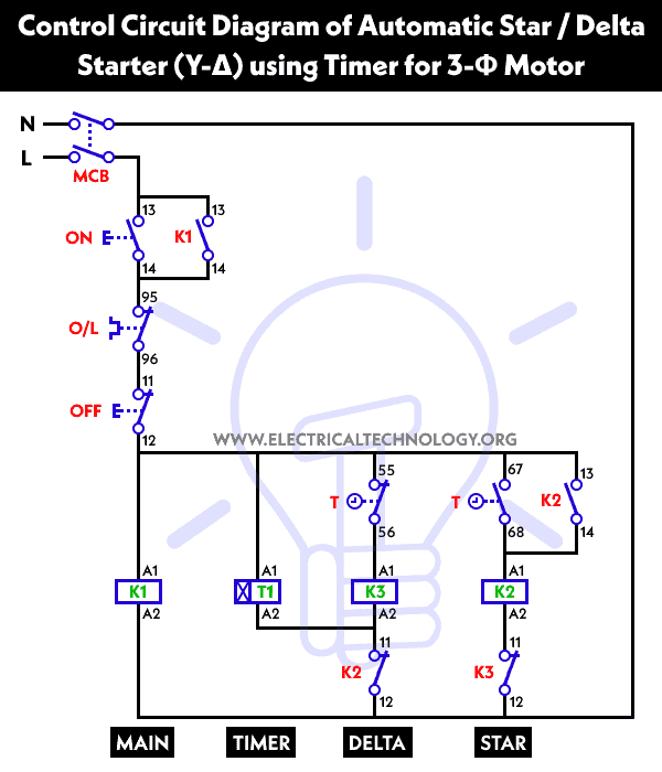
- Initially, the PLC reads the status of two push buttons, namely “ON” and “OFF”. Once the “ON” button is pressed, “Q1” switches on and coil “K1” becomes energized, causing Timer “T1” to Start counting time.
- Simultaneously, when “Q1” turns on, it triggers “Q2” to turn on. This results in the energization of contactor “K3”, causing both contact “K1” and “K3” to close. Consequently, the motor Starts running in Star mode.
- Upon reaching the preset time of 5 seconds, “T1” opens its normally closed contact, causing “Q2” to switch off and “K3” to open. At the same time, “T1” normally open contact closes, and “Q3” switches on, causing contact “K2” to close. This leads to the motor running in Delta mode.
- Finally, if the “OFF” button is pressed, “Q1” switches off, and the circuit stops functioning.
Related Posts:
- Star – Delta Starter Motor Control Circuit Using S7-1200 PLC
- Automatic Star – Delta Starter Motor Control Circuit Using LOGO! V8 PLC
Wiring Diagrams of Start-Delta Starter Using Different PLCs
Wiring Diagrams
Wiring Diagram of Star Delta Starter using PLC – AC/DC/Relay
Click Image to enlarge

Wiring Diagram of Star Delta Starter using LOGO! V8 PLC
Click Image to enlarge
![]()
Wiring Diagram of Star Delta Starter using S7-1200 PLC
Click Image to enlarge

Star Delta Motor Control Circuit using Omron PLC ZEN Programming Relay
Click Image to enlarge

Star Delta Motor Control Using Schneider Zelio Logic PLC Smart Relay
Click Image to enlarge
Star Delta Motor Control Using DVP 14SS2
Click Image to enlarge

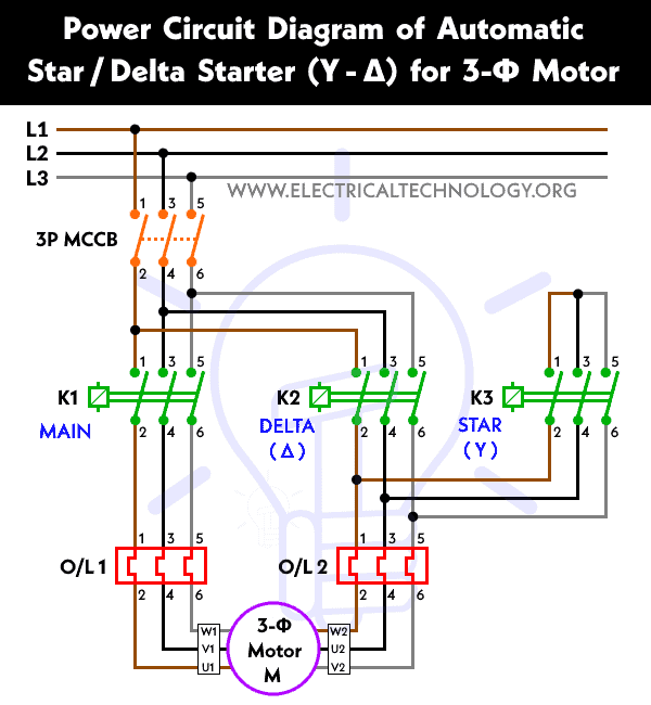
Power Diagram
Control Diagram
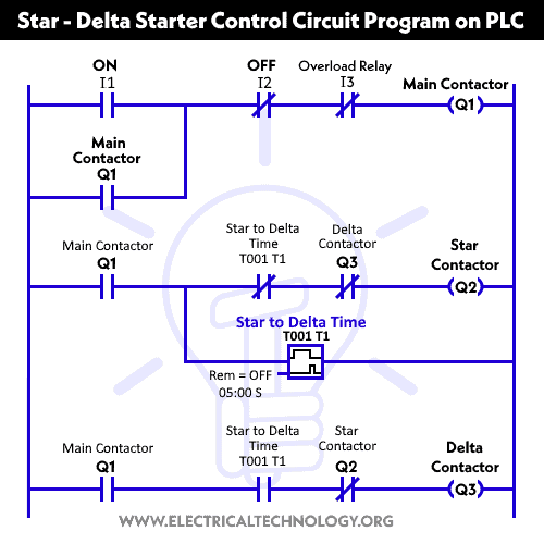
Ladder Diagram
Related Posts: Star – Delta Motor Control Circuit Using Omron PLC ZEN Programming Relay
Programing the Star Delta Starter Using PLC
Following are the details of each rung in the ladder diagram of Star Delta starter using PLC.
Main Contactor
The operation of the main contactor is reliant upon three input devices: the normally open Start push button (I1), the normally closed stop button (I2), and the normally closed overload relay.
In order to activate the main contactor, the Start button “I1” must be pressed while the stop button “I2” is not pressed, and the overload relay remains inactive.
To ensure that the motor remains running even after the Start button is released, a normally open “NC” input labeled as “Q1” is added in parallel with the START button. This creates a push-button functionality that maintains the motor’s operation until the STOP button is pressed or the overload relay is activated.
Star Contactor
The energization of the Star contactor is dependent upon the main contactor, the normally closed contacts of the timer “T1”, and the normally closed contacts of the Delta contactor “Q3”.
As a result, the Star contactor will only activate if the main contactor is turned on, the time output is inactive, and the Delta contactor remains de-energized.
Timer T
The timer “T1” is responsible for measuring the duration after which the winding connection of the Star Delta Starter needs to be switched. The timer begins counting time as soon as the main contactor is energized.
Delta Contactor
The energization of the Delta contactor is dependent upon the activation of the main contactor (Q1), the activation of the timer “T1”, and the de-energization of the Star contactor “Q3”.
The Star Delta Timer is essential for the efficient and safe operation of electric motors, particularly in applications where high inrush currents are expected. With the help of a PLC, the switching of the motor between the Star and Delta modes can be automated, thereby ensuring a smooth and controlled Startup.
Related Power & Control Wiring Diagrams for Motors
- Automatic Star-Delta Starter using Timer – Power, Control & Wiring Diagrams
- STAR/DELTA Starter Without Timer – Power, Control & Wiring Diagrams
- Reverse/Forward Circuit for Motors using Start Delta & Timer – Power & Control Diagrams
- Automatic Sequential Motor Control Circuit – Power & Control Diagrams
- Automatic Reverse Forward Motor Control Circuit Using Delta – DVP-14SS PLC
- Automatic Reverse – Forward Motor Control Circuit Using Omron CP2E PLC
- Reverse / Forward Circuit for 3-Phase Motors – Power & Control Diagrams
- ON / OFF Three-Phase Motor Circuit – Schematic Power, Control & Wiring Diagrams
- Sequential Motor Control Circuit Using PLC S7-1200
- Automatic Sequential Operations of Motors – Power, Control, PLC & Wiring Circuits
- Even More Motor Control Circuits and Diagrams


I need to learn PLC programing with wiring connections.